Sunday, October 29, 2023

Forward Covers (2)

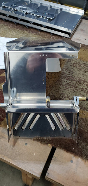
I dug through my boxes, and in the box with my fuel boost pump, I found additional instructions for how to modify the tunnel cover to accommodate the pump and filter.  Then it was off to the parts pile to locate the parts for it.  Whereas the normal cover for carbureted engines is just a single sheet that goes from the firewall back to the fuel selector cover to cover just the fuel lines going forward, the setup for the fuel injected engine requires a larger aft box to also cover the fuel pump and filter.  When I bought the pump kit, it came with a few extra parts that I finally found this morning after realizing there must be something additional I was missing in the standard directions.

To start, the long tunnel cover had to be cut and mated up to a new aft piece that is made of much heavier aluminum and has brackets cut out and bent where the pump and filter will set and be clamped down.  I also had to cut a big opening in the aft portion of the front tunnel sheet to allow the fuel lines to dive down from the pump and go under the cover.


The box that covers the fuel selector valve and all of the associated plumbing also needed to have a big hole cut into the front of it to allow routing of the fuel lines to the pump/filter.


Here's the overall setup with the additional pump/filter cover.  The part that took hours was after I removed it from the plane.  The modification requires a bunch of nutplates to be laid out and riveted on so all of this will be "easily" removable.  Nutplates are easy, but just very fiddly and take a while, between drilling them with a jig, dimpling all of the parts and riveting them on.


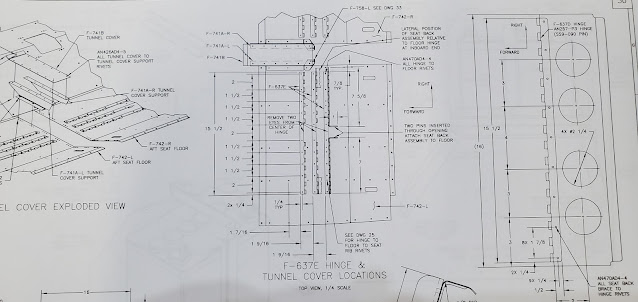
The sides of the tunnel covers attach to the floor stiffener ribs with nutplates and screws.  I was able to match drill through the pieces uses a 1/8" bit in my angle drill, but I don't have the right size drill bit for a #8 screw (a threaded bit that will go in the angle drill at least), so I couldn't finish the holes in the floor stiffeners.  Threaded bits are harder to come by and pretty pricey, so I ordered a hex head bit in a fractional size that is close enough to the typical #19 to work.  I have a hex head angle attachment that I can use for my drill.  It's much bigger than the pneumatic angle drill, but it'll be good enough to upsize the holes I already drilled.

I pulled all of the parts out of the plane, and after all of the nutplates were finished, I threw them on the pile for priming.  That's going to be a loooong day this coming spring!  Next up, the housing and setup for the electric flaps.

Saturday, October 28, 2023

Forward Covers

The center of the floor in the forward fuselage is where fuel lines and a lot of wiring will route through.  There is a cover that fits in between the flooring angle stiffeners to go over the area, as well as tie into the "heating system" on the firewall.  Even though I usually don't rivet things together or put on nutplates until after I've primed things, there's really no option in this case.  Everything is removable, so held together by screws.  Without the nutplates riveted on, fitting things would be a lot more difficult.  So I'm continuing on with the approach of just putting a little primer on mating surfaces and assembling what needs to be assembled.  I'm going to have a decent pile of assembled parts to prime at some point!


The forward vertical portion of the cover has cutouts on the front and sides to direct heat into the cabin.  I bent all of the tabs out a little to better direct air.


It's a little hard to see, but a heat baffle is riveted on just below the vents to direct the air out the vents vs into the center tunnel.


After attaching lots and lots of nutplates, I did a trial fit in the plane.


Next up were the parts that house the fuel selector valve.  It was at this point that I paused and just stared at the whole thing...I'm not sure that this setup is right for an injected engine.  The fuel boost pump on the injected engine sets in front of the fuel selector valve and needs a housing over it.  I'm wondering if the instructions don't call this out, but somewhere sitting in a bag I have different parts that I have to figure out.  Time to take a break and sort through piles to see what the deal is.


Tuesday, October 24, 2023

Seats Done!

I ran out to the shop for a few minutes tonight to finish up the top two rows of rivets on the seat backs using the c-frame.  Now you can finally see how everything goes together with the seat back hinges mating up to the hinges attached to the floors.  I haven't put the top seat back braces in place yet (these attach at the hinges near the top of the seat frame) because I'm not sure they'll be necessary.  I know a lot of people just leave them out.  It just depends where I end up locating the bottom of the seat back on the floor.  In the aft most position, having the seat brace in place would essentially make the seat vertical, whereas leaving it out still allows the seat to be slightly reclined by resting directly on the seat bulkhead.  If I end up using one of the more forward floor hinge positions, then the top brace may be needed to keep the seat from reclining quite so far.  I'll just have to wait and see how it all feels once I have cushions in place and see how much leg room I need.


Monday, October 23, 2023

Seat Assembly

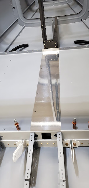
Here's the forward tunnel cover assembled.  Since it's held in place with screws, I'll just put it in place temporarily for now and then pull it out to prime and paint next spring when the weather warms up.


I came close to getting the seat backs finished.  Everything is riveted together except for the angle on the top edge (under the lip) and the top piece of hinge that the seat back brace connects to.  I didn't do those with everything else because I need to change my riveting setup to reach the rivets.  I used the squeezer on everything else, but I either have to use a gun or the c-frame for the angle and hinge.


Sunday, October 22, 2023

Seat Tunnel & Priming

The next step after temporarily mounting the seat pans was to fit the parts for the front tunnel cover.  This is made up of two Z brackets with a ton of odd angles cut into them, and a thin plate that rivets to the top of them.  It all gets attached to the seat pans with screws.  Instead of trying to lay out all of the holes with it in place, I decided to just locate a couple of them for reference and then drill the rest with the parts out of the plane.


Yesterday I had glued down a couple of cable tie mounts that will help hold the conduit in place under the seat pans.  The glue seems to be holding just fine, so I zip tied the conduit to the mounts.  With that done, there's nothing keeping me from permanently attaching the aft seat pans.


The seat pans get attached with pop rivets since there is no way to easily access the back side for regular solid rivets.  It was a pretty easy process, other than the back ache from bending over the side of the plane and reaching inside for an hour.  I see why some people have gone the route of building a rotisserie to attach the fuselage to.  Being able to rotate it would definitely make access a lot easier.


The front section of the tunnel has a bunch of parts that attach with screws, so after a brief rest for my back, I went back in to attach all of the nuplates.


I had my fingers crossed that we might get a little sun to kick the temps into the 60's, but no luck.  I've ordered more of the EkoPrime, but for now all I have left is the epoxy primer.  Unfortunately, it is a lot harder to spray in cold weather (supposed to be at least 70 degrees for that).  Most of the parts I have to prime are removable, like the seats, baggage panels, and the rear baggage bulkhead.  I still need to assemble things like the seat backs and the front tunnel cover, and I don't want primer to hold up progress.  So while it looks like a 2 year old did it, I took a paint brush and dipped it into my little touch up container of EkoPrime and just brushed primer on all of the mating surfaces.  Since the EkoPrime dries reasonably well in the colder temps, I will at least be able to assemble everything and move on.  Once I have some warmer weather next spring, I can prime all of the parts as full assemblies.  The reality is these don't need primer for corrosion control, given they're all non-structural parts that won't be exposed to the elements.  Most of these particular pieces will be visible to some degree though (or will get wear and tear), so I will be painting them and will need the primer for that anyway.


Saturday, October 21, 2023

Seat Pans

In between house chores I managed to get a little shop time in today.  The seat hinges are made of really soft aluminum that is known for getting serious waves in it when riveted.  Instead of trying to somehow hold the seat pans vertical while riveting (this "normal" riveting is what leads to the waviness of the hinges), I decided to use the C-frame dimpler.  This is a little slower, but it produces really nice rivets because the rivet gun and the rivet set on the bottom are always in alignment.


The plans say to rivet the seat pans in at this point.  I had just glued down a few cable tie mounts to the floor underneath to zip tie the wiring conduit to.  It takes 24 hours to cure, so for now I'm just going to cleco the floors in place.  The front seat floors (that go under your legs) are removable and held in with screws. I put a few screws in place just to get everything lined up for the upcoming parts, but they will have to come out again shortly to put the controls in (as well as to paint).


Sunday, October 15, 2023

Seats & Front Tunnel Cover

I've been doing tiny chunks of work the last few days and need to get caught up with pictures.  I finished the hinge halves that will get riveted to the seat pan and match drilled them.  These mate up to the other hinge half on the bottom of the seat back and provide a few inches of adjustment fore/aft.


The seat backs have a surprising number of parts.  The main seat back is just a thin corrugated sheet, so it needs to be stiffened up with aluminum angle - 2 thick pieces for the sides and 2 thinner pieces for the top and bottom.  I started by cutting up raw stock for the side stiffeners.


The bottom of each side stiffener traps the hinge that mates up with the one riveted to the seat pan.  I notched out just enough material so the hinge will fit between the stiffener and seat back.


To be able to adjust the angle of the seat, a brace gets attached to the upper portion of the seat back using a hinge.  This movable brace slots into the different locations in the seat back bulkhead that I built a long time ago.  I trimmed the pieces according to the plans and then drilled the optional lightening holes (no real reason - I suppose now I can carry two extra crackers because of the weight savings).  I didn't have a hole saw the size called out in the plans, so I used a fly cutter at first.  The first hole was fine, but cutting the second hole I really made a mess of things because the fly cutter wouldn't stay centered.  The material is soft enough that the centering bit of the fly cutter was chewing away at the hole and making it oblong.  So the fly cutter wandered pretty bad.  I stopped and decided to finish up the holes with the largest hole saw I have.  It's only 1/4" smaller, so is barely noticeable.  I should have just started with the hole saw and left the fly cutter in the drawer.

I didn't take a picture of the fly cutter damage.  This part is non-structural, so I just mixed up a little JB Weld that I had and filled the stray gouges.  Once it set up, I sanded it smooth the next day.


All of the hinges and stiffeners cut and ready for holes to be drilled:


The top of the seat has a lip with an angle stiffener that nests inside of it.  A few inches below that is the hinge that connects the moveable brace.  The bottom of the seat also has an angle stiffener.


The moveable brace:


I deburred all of the parts and added them to the pile to be primed.

With the seats done, next up is the forward tunnel cover.


The tunnel cover supports are made out of extruded Z angle with lots of angles cut into them.  I laid out and made the left side and called it for the weekend.


Sunday, October 8, 2023

Baggage Panels & Seat Hinges

Since the seat floors will go in soon and cover the conduit up, I put RTV around where the conduit passes through the bulkheads. It's purely a belt and suspenders kind of thing - it makes the conduit fit a little more snugly in the hole, which will minimize the chance of the metal cutting through the plastic and chaffing wires due to vibration. Van's said to do it on the conduit in the wings, so I figured it made sense to do it here as well.


A simple panel covers the baggage tunnel.  There was really nothing to do with it other than set it in place to verify the holes line up with the nutplates.  I'll prep it for installation, but it won't go in until the plane is pretty much finished.


The fore baggage side panels come mostly finished, but for whatever reason, the top flange is not cut to size.  I can think of no reason that Van's would do this other than as a way to meet the 51% rule.  I chopped it down and slid it into place to check the fit.  This panel is also removable to allow access to the flap controls rods.


I'm starting to get a bigger pile of parts to prime, but I'm still going to do some more work before I have a full priming day.  I am out of my grey EkoPrime, which is by far my favorite primer.  I do still have some of the much lighter epoxy primer, but I think I'm still going to need a little bit more to finish everything.  I ordered one more quart of the EkoPrime and a quart of paint as well.  There's not going to be much of the interior to actually paint since I'll have interior panels and carpet in most areas, so hopefully a quart does it.  I tried a test piece of the "professional" Rust-oleum spray enamel, but after two weeks it's still not cured and can be scratched with a very light rub of a fingernail.  I'm going to give Stewart's paint a try (the same company that makes the primer).  It's a standard waterborne acrylic urethane and should be far more durable.  It's way more expensive ($110/quart), but for just a quart I didn't cry for more than few minutes.  I need to get used it - when it comes to exterior paint, I'll be paying thousands of dollars for just a few gallons of paint (each gallon doubles in cost because you also have to buy an equally expensive catalyst)!  It's pretty crazy how expensive paint is these days!

Next up are the seat pans and the hinges that are used to make the seating positions adjustable.  Basically, the seat pan gets half of the hinge material riveted on to it and the seat back gets the other half.  The standard setup is to have 3 different hinge locations on the seat pan so you can move the seat back fore and aft about 3".  It'll make more sense once I have it all together and can show a picture.

The hinge material comes in long lengths that have to be cut down.  I pulled the hinge pin out and started measuring and cutting.  I've heard many people talk about the gotchas of this area, so I paid extra close attention to the drawings (the instructions don't provide much more than a generic "build the seats").


The drawings are very detailed, but I can see how they can bite you if you don't pay attention.  You have to make sure you cut the hinges in the right places so you have eyes that are where they need to be, open spots where necessary, and on and on.  Each seat floor gets 3 hinge halves.  I cut 6 to the right lengths, then laid out where they go on the seat floor.  Then the hinges have to be drilled for riveting.  It's amazing how much time it takes to do something as simple as laying out rivet lines and drilling them.  I have a lot of respect for people who built these planes prior to the existence of pre-punched parts!  I don't have a picture, but I ended the day with clamping the hinges to the left seat floor and match drilling the floor to them.


Saturday, October 7, 2023

Baggage Bulkhead

The upper portion of the baggage bulkhead has to be trimmed to fit within the curve of the fuselage.  I laid out the curve and cut it using a cutoff wheel on the die grinder.  Then I put the lower and upper pieces back in the fuselage and drilled the remaining screw holes in the fuselage bulkhead.


Once I had the screw holes located, I removed the upper skin to make drilling and riveting the nutplates easier.  It's pretty amazing how floppy the fuselage bulkhead gets without the skin in place.


The seatbelt cables have to go through the baggage bulkhead where the upper and lower parts meet.  I cut out the clearance holes, then made the plastic blocks that get pop riveted on to protect the cables from rubbing against the metal of the bulkhead.


The two blocks come together on the back side of the bulkhead and provide just a small opening for the seatbelt anchors to pass through.  I don't have enough parts to justify another priming session yet, but I went ahead and installed the blocks anyway just so I could keep things moving.


Sunday, October 1, 2023

Baggage Area

Since I put two extra conduit runs under the baggage floor area yesterday, I decided to go ahead and close everything up.  I'll leave the seating area floors unriveted until late in the project since there will be a lot of wiring and potentially a few antennas mounted under that area (the front seat floors are removable, but the aft seat floors are riveted down).  The baggage floors are mostly pop riveted, with the exception of the nutplates for the center tunnel screws.


The rear baggage bulkhead is made up of two  corrugated sheets that screw into the 706 bulkhead.  I matched up the pre-punched screw holes on the bottom edge.  There area no screw holes or nutplate holes in the sides/top of the 706 bulkhead.  I clamped the sheet in place and drilled the main screw holes up the sides.


After the main screw holes were done, I drilled the rest of the mounting holes for the nutplates, then deburred, dimpled and riveted on the nutplates up the side and in the center channel.  There are still a lot more nutplates to do, but I have to finish the top part of the bulkhead wall first.


The larger bottom portion of the bulkhead wall pretty much stays as-is.  The top part has to be cut to match the curve of the top of the fuselage, and all of the nutplate locations laid out based on dimensions shown in the drawings.