Showing posts with label Rudder. Show all posts

Saturday, March 2, 2024

Rudder Fit

This week I received the missing rod end bearing for the lower rudder hinge.  I screwed it in to the suggested depth and did one of about 20 trial fits to the vertical stabilizer.  


With the forward spar of the vertical stab in front of the mounting bracket, there was about 1/16" of bow to the rear spar.  That doesn't sound like much, but because of the slight variations in holes in the rear spar hinges, this bow ended up making the center hinge hole about 1/8" too far forward.  I didn't want to back out the middle rod end bearing that much (and it would probably cause some binding being that far off of the center line), so I removed the vertical stab and attached it to the aft side of the mounting bracket.  This is a suggestion in the manual, so apparently not all that uncommon.  I had tried this once before and wasn't happy with the result, but with everything bolted down now, this actually lined the hinges up much better.  There was almost no bow to the rear spar, so I was able to play with the screwed in distance of each rod end bearing to get them lined up pretty well.


Even though the hinge line was pretty good, I still had to take the rudder off multiple times to get all of the bearings at the right distance so the rudder could swing freely from stop to stop without binding.  It was fine except for the very bottom where the rudder's control horn connects.  The way they designed that pushes the skins out on both sides, so as-is it rubs the vertical stab at full deflection.  After some fiddling I got it to clear ok.


Next up was putting the elevators back on to measure the total deflection of the rudder in relation to the elevators.  I didn't bother bolting the elevators to each other since this was all temporary.


The instructions indicate what the measurement should be from the rudder's trailing edge to the outside trailing edge of the elevator when the rudder is at full deflection.  Thankfully, it came out perfectly, so no more fiddling.


As much as I'd like to bolt everything together at this point and call it done, there's just not enough room to move around with the tail on.  I dismantled it all and moved the parts back upstairs.


Sunday, October 24, 2021

Rudder Trailing Edge

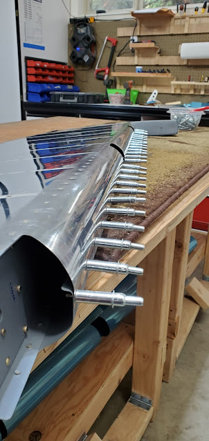
I bit the bullet and set the rivets on the rudder trailing edge.  The tape is supposed to hold the skins and wedge together while you rivet, but it really didn't work out that way. I'm not super happy with how they came out, but after licking my wounds and talking to some guys on the VAF forum, I learned that I'm in really good company and most people have very similar experiences on the trailing edges.


The trailing edge on whole is within the spec in terms of being straight, but the skins pillow a bit in between the rivets (and sometimes at the rivet too if the dimples and countersunk wedge don't sit right).  Consensus is that this happens all of the time if you just follow the Van's directions.  It sounds like significant experience and learning through error are the only ways to correct this.  Most people suggested just leaving it, but some have gone the extra step of filling the gaps with fiberglass/epoxy and sanding smooth.  I'm setting it all aside for now and will figure out what to do down the road when I work on all of the fiberglass and body work for the plane.  As with most aesthetic items so far that bug me, this is yet another one that will only be noticed by someone looking for it specifically.


Following the trailing edge, I finished the leading portion of the rudder. In order for the rudder to sit within the recess of the vertical stabilizer, you have to bend the skins and rivet them together to form a curve.  I used a 1" broom handle taped to the skin and rolled the skin until it was close to the desired shape.


I made the mistake of assuming that the #40 prepunched holes in the skins were the right size and match drilled them all at that size.  Then, as I usually do, I referenced the plans to see which rivets to grab.  Oops.  Turns out they are 1/8" rivets, which means I had to redrill at #30.  Not a big deal, but one of these days I'll have to remember to look 2 steps ahead before finishing a step.

With that, the rudder is pretty much done.  The only items remaining are to attach the bearings that marry it with the VS, but I'll wait and do all of that when I put them on the fuselage.  I'll also wait and do the fiberglass tips down the road once the plane is largely finished.

Next I'll tackle the elevators.  I'm a little nervous about the riveting on the elevator spars just because of the access and the pre-bent skins, but from what I'm learning from all of the other problematic areas I've hit, it's unlikely I'll do any worse than others who have gone before me and still have flyable airplanes.  I'm definitely my own worst critic.  Even when I know a mistake I've made is really no big deal (like slipping off a rivet and dinging the metal next to them), I shake my head because I know I've made an avoidable mistake.  I suppose it's healthy to have that mentality when building a plane, but I need to learn to just smile at goofs and count it as part of the experience.


Saturday, October 23, 2021

Rivets In Tight Places

I got my new 4" no-hole yoke attached to the squeezer so I could tackle a few of the rivets in tight spaces.  In general, the yoke worked really well, but even with it, there were rivets I couldn't squeeze because the space was too tight.


I think the lesson for today is that if the manual says that blind rivets are an option, there's a very good reason they're an option!  Getting into the last hole of the rudder ribs may have been possible with a very small bucking bar, but the end result would likely be iffy at best.  So from here on out, in all likelihood if a blind rivet is allowed, I'll probably use it.  It's funny how some builders seem to think that if you use a blind rivet you're less of a builder.  To me, it's a reasonable tradeoff of time.  If the hole in the rivet bugs me, I'll just fill it before I paint, but honestly, I don't think it'll even be noticeable.  You can see the pop rivet next to the sharpie "R" in the picture.  There are a lot of different types of blind rivets specified, but these specific ones are for dimpled holes, so they are flush, just like a solid rivet would be.


On the second side of the same rib I found that I had to use a blind rivet in the last 2 holes vs just the last hole on the first side.  That's because once the solid rivet in the 2nd to last hole was set, it created a smaller space that the no-hole yoke no longer fit in.  Again, these are going to be at the top of the rudder though, so depending on what color of paint I end up with, probably next to impossible to see.


The last bit of riveting on the skeleton of the rudder was to attach the rudder horn cover.  I was able to get 3 of the 4 rivets to the skin squeezed, but my longeron squeezer wasn't long enough to get the very back one.  Again, blind rivets are allowed, so that's what I used there.  For the 3 rivets that are at the aft edge of the cover (connect the tongue of the cover to the rib - pointing to the left in the picture), Van's calls out solid rivets with the option of blind rivets.  Because I didn't install the cover until after closing the skins, there is no way of accessing the back side of these rivets.  Had I put this cover on part-way while I was building the skeleton, I could have used solid rivets I guess.  I just left it off because I knew it needed to be riveted to the skins.  So maybe on airplane #2 I'll remember that I could attach this piece earlier using solid rivets, but for this plane, the acceptable blind rivets will do just fine.


Now for the trailing edge.  This is slightly nerve wracking since I need to get an arrow straight trailing edge with less than 1/10" of variation from straight at any point over the 4' span.  I'm sure it'll turn out to not be that big of a deal to do, but it's a brand new kind of task and riveting.  To start, the recommendation is to adhere the wedge between the skins vs just riveting right away, which can cause warps.  Van's used to recommend using proseal to stick the skins together to the wedge, letting it dry while clecoed to a piece of aluminum angle (to keep it all straight), then rivet after it set up. They now recommend using 3M VHB tape instead since it's a lot less messy.  After seeing the tape, it blows my mind that it can do any good.  It's a double sided tape that is so thin I was questioning if there was anything on the backer paper.  I cleaned the wedge with acetone and stuck the tape down on each side.  


Once the tape had set for about 20 minutes (supposedly gets stronger the longer it sits), I slid the wedge between the trailing edge of the skins and pulled about an inch of paper off the bottom side of tape.  I can't remember if I mentioned this yesterday, but I had prepared a piece of aluminum angle by drilling holes into it that matched the spacing on the skins. I clecoed through the skin, wedge, and aluminum angle in the last hole on each end of the skin, then peeled back the rest of the tape.  Then I repeated the process with the tape on the top of the wedge.  Once the tape's backing paper was completely removed, I clecoed all of the holes to the aluminum angle.  I'll let it sit overnight and hopefully the tape will do it's job and help to keep the skins in position and straight when I rivet tomorrow.  Fingers crossed.  It's really hard to believe that tape does anything, but apparently it's pretty amazing stuff once it gets bonded. 


Friday, October 22, 2021

Rudder Trailing Edge

I haven't been able to do much more on the rudder or elevators until I get the new 4" yoke.  That has me twiddling my thumbs a little bit, but now that I have everything primed, I went back to finishing the rudder.  The last piece (aside from finishing the rivets I need the yoke for) is to do the trailing edge.  I countersunk the holes in the wedge that goes in between the skins at the trailing edge.  Doing this by hand is known to be problematic because the material is thin enough that when you do the second side the hole enlarges and the countersink flute wanders.  Dad and I had set up the drill press before he left, angling it so that the cage matched the angle of the wedge.  This worked great.  It was very easy to countersink the wedge.


It's too late to get any additional work done tonight, but as I'm writing this, the UPS man brought my new yoke.  This is a 4" throat, whereas my biggest throat up to this point was 3".  It also does not accept a die on the upper nose.  It is solid, meaning you can squeeze rivets right up against the nose, allowing squeezing in tighter spaces.


Thursday, October 14, 2021

Rudder, Part 35

There's not much to show for progress today.  I riveted the rudder skins to the spar and finished up as much of the top and bottom rib riveting as I could.  The last couple of holes in the tips of the ribs are too tight for squeezing or normal bucking.  I think I can get at those with some creative back riveting using the piece of 1/8" steel bar I bought at Home Depot for this exact purpose, but I didn't have the energy to deal with it tonight.  This is one of those things that will take an hour to get the right setup figured out, then 5 minutes to rivet.  That seems to be the norm, so I'm starting to get used to that approach.

I still have to attach the rudder control horn cover.  From what I've read, the 8 or so rivets that attach it to the rib/skin are very difficult to get to because the only access is through a lightening hole.  I may be able to get one or two with my squeezer, but we'll see.  Worst case scenario, the plans do call out that blind rivets are ok for those holes, so that might be what I end up doing.  We'll see.  I'd rather use solid rivets whenever I can, but let's face it, nobody would ever know the difference and it doesn't make a bit of difference in terms of structural integrity.  I have a feeling I'll make more and more of those tradeoffs as I continue through the plane.  It's kind of silly to spend hours vs 60 seconds on a task for no real practical benefit.


Wednesday, October 13, 2021

Rudder Continues

Tonight's tasks were the perfect example of why, while an RV is relatively "easy" to build, it still takes far more time that it seems like it should.  The instructions are already starting to get more and more sparse, so it feels like I'm spending as much time trying to find callouts on the plans as I am building. It probably took me a good 10 minutes of staring at the plans before I finally found the note indicating the rivet sizes to use for the nut plates that attach to the spar and are used to capture the rod end bearings.  All of the information is there, but it just takes a while to piece it together sometimes.  

Once the spar was all done, the counterbalance rib was riveted on.  That's when I hit another 2 minute task that took 30 minutes.  The lead counterbalance weight gets inserted into the counterbalance rib and attached using two nut plates.  This requires prepping the aluminum stock, countersinking it for rivet heads that need to sit flush against the counterweight, priming it, riveting the nut plates on, then assembling everything.  The "assembling everything" part took another 15 minutes though, because the lead was just a bit to wide at the front, so I had to file off a little bit here and there so it would clear the rivets in the skin and the screws would hit the nut plates.  So all in all, an extremely simple task, but just took forever.


After the counterbalance weight was finished, the skins go back onto the spar.


I clecoed the skins to the spar and called it a night.  I get pretty lost in building, so it'd be very easy for me to be trucking along and not realize it's midnight.  I have forced myself to set an alarm to ensure that I end at a reasonable hour and don't get too carried away.  I need to at least be somewhat functional in the mornings for work so I can pay for this contraption.


Tuesday, October 12, 2021

Rudder

I didn't have a lot of energy to spare today, but figured I could get the low-key riveting done putting the stiffeners on the rudder skins.  This is a different kind of riveting than I've done up to this point - back riveting.  It's pretty much dummy proof in terms of getting beautifully flush and flat rivets. To back rivet, you put your rivets into the dimples in the skin, put tape over them to keep them from falling out and turn the skin over.  With the rivets sticking up through the skin, the part goes on and the rivet is set using the gun on the shop head side (the part is placed on a large steel plate that is used to keep the rivet solid and flat).  The rivet set in the gun is a little different - it's a thin, spring loaded flat set with a collar around it.  The collar is able to move up and down because of the spring, so it keeps you centered on the rivet.  It's very easy to make quick and pretty rivets this way.


The back riveting didn't take very long, so I started putting the reinforcement plates on the spar.


I got to the rib and rudder horn and had to pause.  When we put this together, we noticed that there are two extra holes in the rudder horn and spar, but not called out in the plans as needing to be drilled through the shim that is between them.  The plans don't show these extra two holes either.  Before I rivet all of this together, I'll email Van's and double check that I don't need to match drill these to the shim and rivet.  I've looked at build photos from other builders and on the older planes these 2 holes weren't even there, so it's something relatively new. 

Update:  Van's responded and said those two extra holes were added for the RV14.  I can leave them empty.


Thursday, September 30, 2021

Rudder & Primer Prep

 We started today by finishing the rudder.  The mantra of "cleco, drill, disassemble, debur, dimple" is becoming very familiar already.


At the lower end of the rudder is a rudder horn cover plate that needed to have the wings cut per plans, then fitted and match drilled to the skins.

I didn't get a picture of it, but we also fabricated two strips to match drill to the lower rib and skin.  These attachment strips are put in place for the fiberglass tips (installed later on).

The last build step today was the fitting of the lead counterweight.  This goes inside of the front counterweight rib at the top of the rudder.

The weather looks like it might be favorable for priming tomorrow, so we made a quick run to Home Depot to pick up acetone.  Fingers crossed that we'll be able to start and finish priming tomorrow.  That's the next big step before being able to start riveting.


Wednesday, September 29, 2021

Rudder

After the stiffeners were finally done, we started the rudder skeleton.  This was pretty straight forward, aside from figuring out how the rudder horn is supposed to layer together with the lower rib.  The plans just don't show the layout in enough detail to determine if the rudder horn goes on top of or underneath the rib flange.


After some back and forth (and looking at a few online build logs), we figured out that the rudder horn sits on top of the rib flange.  In hindsight, that makes sense given that there is a shim behind the rest of the rudder horn, which is there to make up the thickness of the rib flange.  The top of the horn had to be trimmed down a touch and rounded over in order to fit with the rib flange bend.

Here, the plans call for the stiffeners to be riveted to the skins before proceeding to the next steps.  I'd rather do all of the priming at once though, so we decided to just cleco the skins on without the stiffeners.

The tip rib and the counterbalance rib at the top of the rudder were a bear to get right!  The material is much thicker than the ribs of the horizontal stabilizers, so it's much more important to flute the ribs as close to perfect as possible.  We had to go back and forth with this a few times.  The ribs are so stiff that if the holes don't line up, bending them in place is not nearly as easy as with the previous ribs.  This was probably the hardest fit of anything done so far.  


The skins have a small tab that fits around the rudder horn.  This was a little too snug for my liking, so we opened it up a bit on each side.


Tuesday, September 28, 2021

Rudder

 Today started by finishing up the vertical stabilizer from yesterday.  It was disassembled and we deburred, countersunk and dimpled all holes and edges.

The rudder was next up on the list. The construction of the rudder is significantly different than the other surfaces we've worked on so far.  It's shockingly light weight! Instead of having ribs for all of the support, there is only an upper and lower rib, and all of the support is actually provided by angles that act as stiffeners. Van's supplies a bundle of angle for the stiffeners. These all have to be cut and shaped to fit the rudder skin.  The manual is woefully inadequate in describing how the full length angle needs to be cut to provide the correct number to match the skins. The pre-punched holes in the skin aren't evenly spaced, which makes it even more of a head scratcher.  After a lot of trial and error, we finally figured out how to place and cut the stiffeners so that they all work out.  Each stiffener gets cut (have to do so from the correct side to make it work out right!) according to marks Van's puts in the angle. We marked, cut, sanded, and deburred the stiffeners and clecoed to the skins.