Showing posts with label Electrical. Show all posts

Sunday, July 13, 2025

ADAHRS

I have to travel for work this week, but I got a few hours in today before heading to the airport.  I've been putting off climbing into the tailcone again to work on the ADAHRS stuff.  The shelf was installed, but the unit itself wasn't bolted to it.  In hindsight, I would have modified the standard ADAHRS shelf and moved it an inch forward to make it easier to install all of the wiring.  The plans have it butting up against the bulkhead, which means there's about 1/4" of space between the back of the D-sub connector and the bulkhead (after the wiring is cranked to a 90 degree angle).  A little more room to work would have been wonderful.  Oh well.

Climbing back into the tailcone was a job in itself.  Getting under the seat brace is easier said than done!  Of course once I was in, I realized there was more work to do than I thought, so I had to do the contortion a few times.  I gave in and removed the elevator pushrod to give myself more room to lay down.

All I really had to do was put 4 little brass bolts and nuts (non-magnetic) in to hold the ADAHRS unit in place.  With barely any room to get my fingers on top of the shelf to hold the nuts, that took a while though.  I wrapped the 90 degree bend of the wiring with plastic spiral wrap and tape to protect it from the shelf, but I'm still not all that happy with how it's setting.  I think I may need to pull some slack into the wire to allow it to bend away from the shelf a little more.  That sounds simple, but of course I tightened all of my wiring down a while back thinking I was done.  I have a service loop at the instrument panel, but I'll probably have to undo the majority of zip ties to pull some slack all of the way to the back.  I'll mull it over and see.  It might just be easier to put some better protection on the wire at the shelf vs undo everything just for one more inch of slack.


Thursday, April 10, 2025

Firewall Doublers

I plan on initially just having a single alternator, but once I set the plane up for IFR (or start doing a lot of cross country flying), I will probably want to add a backup alternator.  I would like that to be a plug and play event vs a big makeover of wiring and firewall work.  I emailed back and forth with one of the tech support folks at B&C, which is a well regarded alternator and electronics vendor.  They were really helpful in explaining the easiest way to set up a dual alternator system using their internally regulated units (vs externally regulated, meaning fewer boxes and less wiring).  I figured out that if I run wiring for a standby alternator switch and put in the nutplates for a second ANL fuse mount, adding the second alternator should be as easy as putting it in place on the accessory pad and wiring it up.

I made a doubler to mount the amp shunt and existing ANL fuse to using AN3 screws.  The B+ lead of the primary alternator will go to the ANL 60 fuse, which will then connect to the shunt.  When I add the standby alternator (likely a 40 amp, since that's what B&C has for an internally regulated standby unit, even though it's far larger than I'd need for a backup), I'll add a second ANL 40 fuse and the standby B+ lead will go to it.  That ANL 40 fuse will then also attach to the shunt.

I offset the mounting location for the two ANL fuses, just to make it easier to route the wires to the shunt without interfering with each other.  I probably should have made the doubler a little bigger so I could spread things out a little bit more, but I had already gotten it all drilled to the firewall by the time I figured out that a second ANL fuse would be necessary with the standby alternator.

This doubler attaches to the lower, right side firewall. One screw from the shunt attaches to a nutplate in the doubler, but the inboard mounting screw of the shunt uses a nutplate on the firewall stiffener.  I had the fuel fitting doubler done and just sitting there, so I grabbed it and prepped it to be riveted to the firewall.  The dimension on the plans won't work though - the top outside corner of the doubler interferes with the start solenoid mount.  I ground away a corner of the doubler and riveted it on.  After that, I put the washer doubler on the fuel fitting, added some fire sealant and torqued it down.

I attached the nutplates and riveted the doubler to the aft side of the firewall.  I also attached the fuel line to the fitting.  I torqued it down, but looking at the picture, realize I still need to add torque seal so I know it's been done.


Sunday, December 31, 2023

Strobes/Position Lights

The Flyled wingtip lighting takes a lot more work to put together than the landing lights.  The circuit boards are the right general shape for the wing tips, but are far from a match.  This isn't the fault of Flyleds - the Van's fiberglass parts are known for being a bit rough. I shaped all of the boards on the sander until they fit.


Step 1 was to bend the tabs on all of the white strobe lights to give a foot to solder to the control boards.


I spread a very thin layer of thermal grease on the back of each LED and then put them in place on the boards.  The thermal grease just helps transfer heat from the LED to the control board.


After soldering the strobe LEDs, the position lights were next.  These things are tiny! Like the strobes, they get thermal grease on the back. The + and - markings on these were incredibly hard to see.  I had soldered one and a half boards before I happened to notice something - the right side should get green position lights.  I had just grabbed the position lights from the little bag marked "G" and not given it a second thought.  It wasn't until I was partially through the second board when I noticed the LEDs had a very, very tiny red dot in them.  It turns out the bags were switched.  The green lights are basically clear in the middle (no green).  I guess that's the joy of solder - easy to undo.  I unsoldered everything and grabbed the green lights from the bag marked "red."  I will say my soldering skills won't win any prizes, but it's serviceable. It all looks a bit dirty from the flux, but I'll clean it up after I'm all done.


With all of the lights soldered in place, next up were the resistors and wiring mounts.  The green position lights get a different resistor size than the red.  The popsicle sticks are simply there to help offset the resistors so they don't lay on the board.  Apparently they build up a considerable amount of heat, so keeping them about 1/16" off the board helps dissipate the heat.


After chopping off all of the resister and wire mount wires, it's time to test!  Even though this is built for a 12v system, the instructions recommend just testing with a 9v battery to keep from burning your eyeballs.  It's shocking how bright these things are!  The one issue I ran into was that on one of the left side boards, one row of position lights wasn't working.  They are wired in series, so after looking at them a bit closer I saw that I had gotten the polarity of one of the lights backwards, which would keep the entire line from working.  After fixing that, everything worked perfectly.  The hardest part of the day was taking a picture with one hand while testing with the other.


The white strobes still have the blue protective plastic on them.  I'll probably just leave that in place until I install everything in the plane.


Saturday, December 30, 2023

Brakes & Landing Lights (2)

Time to run the brake lines! The brake line exits the fuselage at the base of the gear tower weldment.  The fitting has a 45 degree angle on the exterior side to parallel the gear leg.


Running the 1/4" aluminum wasn't too bad, although it's virtually impossible to make it straight.  It comes shipped in a coil, so by the time you uncoil it to start running it through the gear tower, then bend and twist it to get the entire length of it through the brackets, it's pretty wavy. For the left side, I flared the outside end first and then threaded the tube through to the center.  That was a lot of tubing to push through (it goes to the center then runs all of the way to the firewall)!  For the right side I started in the center and just pushed the smaller length to the outside, then flared the tubing in place.
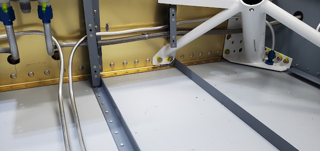

I gave up trying to use the tubing bender to make any of the bends in the center section or at the firewall.  It was easier to just put the spring bender on and bend them in place.  It looks a lot better in person than in the pictures at least.  Van's suggests sandwiching the center runs in between a couple of pieces of foam to stabilize them, but I think I'll probably just glue down a few zip tie mounts instead (I'll wrap each line with some silicone tape to pad them under the zip ties).  The entire center tunnel of the floor ultimately gets a cover to hide everything.


At the firewall the lines exit from the center cover and pop up and over the firewall brace and over to the fittings that tie them into the actual brake pedal lines.  The lines that go to the brakes are nice, teflon stainless braided lines.


A few days ago I stopped working on the brake pedals because I was two bolts short.  I ordered new bolts, which haven't arrived yet, but in the meantime I stumbled on a random bag of hardware and there were the bolts!  I guess you can never have too many extras.  After bolting the left pedals to the brake cylinders, the next step was to put all of the elbow fittings on the cylinders. 


Most of the fittings are brass elbows that connect to the plastic brake lines, but the last fittings in the series (brake reservoir to right brake cylinders to left brake cylinders to brakes) are normal AN fittings that connect to the braided lines I installed on the firewall. I used Loctite 567 sealant on all of the fittings.


According to the drawings the AN fittings for the braided lines need to angle outwards instead of inwards like the other side.  I will have to wait and see how this ends up working.  I don't want the braided lines hanging over the pedals at all where I could accidentally catch them with my feet.  My guess is there isn't enough room to angle them together towards the center though. I'll figure it out with some creative zip ties locations.


It seems kind of flimsy, but the connection through the firewall to the brake fluid reservoir is just a plastic T fitting.  It's a lot like the pitot/static fittings that the plastic lines snap into.  I suppose in reality there shouldn't be significant pressure going this direction to T, and it just needs to be leak free to keep the brake lines full.


Last up for the brake assembly was to run all of the plastic lines (I guess they're not really "plastic" - pretty tough stuff).  These connect to the elbow fittings by inserting a brass ferrule in the line using heat and tightening it all up using a nut and compression ring. I drilled holes in the center hanger and put snap bushings in place.  The lines from the right side bottom cylinder exit connect to the top of the left cylinder.  The lines coming from the brake reservoir connect to the right side top elbows.


That's it for the brakes for now.  They're pretty much ready to install in the fuselage and plumb.  I'm going to wait to do that until I've got as much done around the firewall as I can though.

For a change of pace I decided to start building the landing lights.  This portion of the lights was pretty straight forward - no soldering like there will be for the strobe and position lights.


Here's the finished product.  These will fit in the leading edge of each wing.  The light with the diffuser on it is the taxi light. The assembly can be wired so that all 4 lights are on for landing, but only the diffused light is on for taxiing to keep from blinding other pilots.


Wednesday, December 27, 2023

Brakes & Lights

I put castle nuts onto each end of the pivot rod on the brake pedals and secured them with cotter pins (this normally takes one bolt on each side, but I threaded and drilled a brass rod so it's a single piece and won't bind with flexion as easily).


The bottom (top in the picture) of the brake cylinders have a tab that bolts to the brake pedal arm. For some reason that tab is curved on one side and the plans call for a stack of washers to fill the space.  I don't like how the washers let the cylinder rock around, so I printed a spacer with a concave surface to match the cylinder shape.  I was short two bolts, so have to wait for a hardware order to arrive before I can finish the other two pedals.


The FlyLeds wing and tail light kit arrived.  It's hard to believe that these tiny LEDs can possibly put out enough light, but apparently they're pretty incredible.  Lots of soldering to do first though!