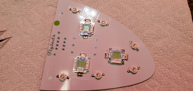
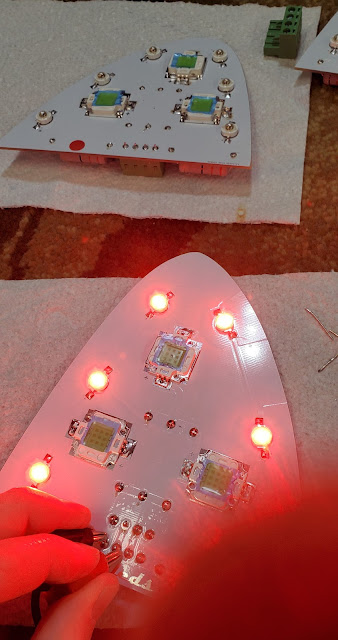
The Flyled wingtip lighting takes a lot more work to put together than the landing lights. The circuit boards are the right general shape for the wing tips, but are far from a match. This isn't the fault of Flyleds - the Van's fiberglass parts are known for being a bit rough. I shaped all of the boards on the sander until they fit.
Step 1 was to bend the tabs on all of the white strobe lights to give a foot to solder to the control boards.
I spread a very thin layer of thermal grease on the back of each LED and then put them in place on the boards. The thermal grease just helps transfer heat from the LED to the control board.
After soldering the strobe LEDs, the position lights were next. These things are tiny! Like the strobes, they get thermal grease on the back. The + and - markings on these were incredibly hard to see. I had soldered one and a half boards before I happened to notice something - the right side should get green position lights. I had just grabbed the position lights from the little bag marked "G" and not given it a second thought. It wasn't until I was partially through the second board when I noticed the LEDs had a very, very tiny red dot in them. It turns out the bags were switched. The green lights are basically clear in the middle (no green). I guess that's the joy of solder - easy to undo. I unsoldered everything and grabbed the green lights from the bag marked "red." I will say my soldering skills won't win any prizes, but it's serviceable. It all looks a bit dirty from the flux, but I'll clean it up after I'm all done.
With all of the lights soldered in place, next up were the resistors and wiring mounts. The green position lights get a different resistor size than the red. The popsicle sticks are simply there to help offset the resistors so they don't lay on the board. Apparently they build up a considerable amount of heat, so keeping them about 1/16" off the board helps dissipate the heat.


