Showing posts with label Engine. Show all posts

Saturday, January 10, 2026

Bottom Cowl & Control Cables

Little by little.  That's the name of the game these days.  I've spent the last few weeks working on cars, so not much time left for the plane.  This past week I chipped away at the lower cowl fit.  It's a bit tougher to deal with by myself than the top cowl has been - gravity always seems to win and makes getting it set into place hard.  It's a lot bigger than it looks in pictures!  I got it set against the fuselage and used the same method for trimming as I did the top.  I drew a line 2" aft of the firewall and then transferred that to the cowl.

The instructions say to just do the bottom portion for starters, but stop before going up the sides.  The idea is to make it match up with the bottom firewall first so you can then always get it into a predictable position before cutting the sides.  I trimmed the bottom, but was definitely conservative.  I'm going to have to do the off and on thing a hundred times to get it right, just like the top. Given how hard that is, I'll probably wait until I have some help.


Shifting gears - I finally received a couple of things I've been waiting on for a long time - the extension kit for the backup alternator and the firewall penetration steel grommets for the throttle/mixture cables.  I bought the grommets because the routing I decided to use for the cables makes them take a big turn through the firewall and the grommets help support them (the grommets are basically a split steel ball that clamps around the cable and can hold them in position).  I pulled the forward top skin off the fuselage so I could get at the aft side of the firewall for drilling.  This would have been nice to do eons ago before the engine was even on, but not knowing where everything would end up going, I didn't want to drill a bunch of holes in the wrong places.


You can see the holes I started below the top firewall stiffener.  I am putting the passthroughs in the angled portion of the inset of the firewall.  Drilling through thin stainless steel is always loads of fun!  I got the screw holes drilled, but my unibit isn't large enough for the center hole.  Guess I need another tool!


This is what I have to show for the next 6 hours of work.  Not much!  Figuring out the exact cable routing took a lot of head scratching.  The cables I got are beautifully made (McFarlane), but as is the norm these days, they won't fit without making some modifications.  The routing for the mixture is going to take it right into the vertical exhaust support.  I decided the best plan of attack was to swap the exhaust support to the other side of the cable bracket (the big, gold bracket).  I moved it from the inside to the outside.  In doing so, I had to make a longer steel tube and a longer rubber hose because now the support has to attach to a different sump bolt.  It's not ideal, because it changes the angle of the support so it's less vertical than it was before, but there's not much else I can do.  I think it should still keep the exhaust from moving vertically.  


The cable bracket has to be modified a little, so I pulled it and the throttle body off and did some surgery on it.  I'm sure after another 6 hours I'll have a single bolt in.

I thought I was going to get the alternator put in, but surprise surprise, I ran into an issue with the studs.  I had been told I could use normal 1/4-20 bolts cut off to make studs, so I bought some and went that route.  Nope.  They thread in with finger pressure alone.  Not exactly what they should be doing!  It turns out the standard Lycoming studs are indeed 1/4-20, but the threads on the end that go into the case are a slightly different shape, even though the pitch and diameter are the same.  That slight difference makes them fit much, much tighter. So in the end, I really need the Lycoming studs to get a good fit.  Back to the waiting game!


Wednesday, November 26, 2025

Hurry Up & Wait

The ELT has a little beeper that goes behind the panel to alert when the ELT is going off.  It is connected to the ELT and to the panel activation switch with standard household telephone wire, which is admittedly a little goofy.  Had I known how this was set up, I probably would have bought a different model, but hindsight is 20/20.  This box has a battery that'll have to be changed out every so often.  It's super light, so I just put some adhesive backed velcro on it and stuck it to the back of the subpanel.  That'll make it easier to just reach behind the panel and pull it down when I need to change the battery.


I attempted to install the backup alternator, but no joy.  The oil filter extension that Titan gave me that bumps the filter aft a few inches to clear the engine mount gets in the way of the alternator.


You can see that the alternator won't seat completely against the accessory pad because the bumps for the bolts that hold the alternator case halves together rub against the oil filter extension.  I got in touch with Titan, and they said they do have a 1.4" extension (vs this 2 1/2" one).  I took some measurements, and that will be right on the edge.  It still might be about 1/16" long, but we'll see.  Worse case scenario, I can take the smaller extension to a shop and have them mill about 1/16" off.  Now I just have to wait for the new part to arrive.  I have to hand it to Titan though - they didn't ask any questions and gave me a UPS tracking number within minutes, no charge.


Saturday, August 16, 2025

Back At It

I need to get caught up on all of the small things I've done over the last few weeks.  I haven't had a lot of time to tackle anything big, but I'm trying to remember that everything has to get done, and small tasks are still progress.

Since the humidity is going to start rising soon and it'll be at least a year before the engine fires up, I decided to pull out the engine dehydrator I built.  I never got the 3D printed valve I was using to be air tight, so I just pulled it out of the loop for now.  I may try to come up with a new valve design at some point, but for now I'm just keeping the dehydrator in the "closed loop" position all of the time.  The air pump pumps air into the oil dipstick tube, then pulls it out from the oil breather line and sends it through a canister of desiccant beads before sending it back to the air pump.  By keeping this a closed loop (vs pumping fresh air through the beads and not having a return line back to the pump), the desiccant will last a lot longer before I have to dry it out.  I will eventually need to get some rubber stoppers to connect the tubing to the engine, but since I don't have any and the dehydrator will stay in place for a long time, I just wrapped the tubing with plastic and taped it in place.  I also taped off the exhaust and air intake to minimize leakage of ambient air into the engine.  So far, the humidity level inside the engine is staying between 20-25%.  From what I've gathered, corrosion pretty much flatlines when humidity is below 40%, so if I keep the dehydrator running, I should be fairly safe to have the engine just sit for a while.

My propeller arrived this week!  This is the Sensenich ground adjustable prop.

There is a spacer that bolts to the prop flange of the engine, then the prop hub bolts on top of the spacer.  The prop blades insert into the hub and the pitch of each blade is set by inserting a pitch pin into the hub and turning each blade until they bump into the pin (each blade has a steel pin sticking out of the base).  It's a far simpler system than most ground adjustable designs, which usually require hours of fiddling with blades and protractors.

I temporarily mounted the spacer and base of the hub (with the spinner back plate), because I need to have a reference for where the front of the cowls need to rest.


Before I get to work on the cowls themselves, I needed to finish the hinge on the right side of the firewall.  The bottom two rivets on both left and right side hinges are buried right next to the engine mount and were next to impossible to buck, so I took the easy way out and used pop rivets there.


Now that I have the prop spacer and know the distance to the spinner back plate, I can finally get to work on the cowls.  I decided to start with something easy - I laid out and cut the oil dipstick door.  It's just a rough cut for now.  I won't finalize it until I'm done with everything else.


True to the internet stories of the last 20 years, Van's fiberglass is a disaster.  The finish isn't horrible, but the fit is amazingly bad.  They outsource the fiberglass parts, and I don't think the molds have ever been right.  I've never heard of anyone who didn't have to do a ton of work on all of the fiberglass parts.  It's so bad that it's pretty confusing about where to start.  I'm doing as much reading as I can.  I'll just have to jump in though.  At least I know that fiberglass can always be fixed.

Just putting the top and bottom cowls together, you can see how off everything is.  I think my first step will be to create a round jig the size of the spinner and get the round nose bowl the right size and shape.  That will guide how much I have to cut off at the sides to get the two pieces to nest together.  In all likelihood, there will be a lot of additive finishing that has to happen once I have it all fit.  Once I have the front fitting, then I'll cut and fit the top cowl to the fuselage, then fit the bottom cowl to both.  I have absolutely no idea what I'm doing.  Should be fun!


Saturday, July 5, 2025

Canopy Prep & Engine Control Cable Brackets

Van's throttle and mixture cable brackets won't work with the Airflow Performance throttle body on my engine.  I found out that as of 6 months ago, Van's is actually now selling all engines with this same throttle body, so I emailed them to ask if they have a new bracket available now.  Unfortunately, they said their engineers haven't had a chance to design a new bracket yet.  I was hoping to get away with a cheaper solution, but in the end had to go to Airflow Performance and buy their brackets.  They are not just gold anodized, but must actually be made of solid gold given the price!  The kit comes with a new plate that sets on top of the throttle body, then two brackets that bolt on the aft sides.  The cable brackets themselves will be drilled to the large aluminum sides.  I put the whole setup onto the engine to see where things fit - it's going to be really tight with the new elastomer landing gear.  That takes up a lot of room that I don't think this bracket was originally designed for.  I'll be able to make it work, but it's going to take some thinking.  I don't have the cables in-hand yet, because I was waiting to order them until I knew what the routing through the firewall will be.  It's a chicken or the egg problem.  Like most things these days, I set it aside and moved on to something else so I could mull over it for a bit.


Back to the canopy - I used the plexi edge scraper to smooth out the edges that I cut the other day then put the canopy on for the 300th time to check the fit.  I think it's where it needs to be in terms of shape.  The next step is to try to mark out where the Sika primer needs to be laid down on the canopy.  It's easier said than done to get inside to mark where the sides meet the frame (so I know where to tape off a line for the primer).  Instead I drew a line on the outside of the canopy at the level of the side skin.  For the aft edge, I went with a measurement taken off the roll bar.  For the front, I'm going to put about an inch high strip of the primer.  The adhesive itself will probably only go up 1/4" or so, but the primer is black and by extending it up an inch it'll help hide the fiberglass fairing that will be on the outside.

Once I had the lines laid out, I pulled the canopy back off and used electrical tape to mask off the areas.  When I'm ready to actually use the adhesive, I'll scuff and prep the edges with the Sika activator, put the primer on and cross my fingers I got it all laid out correctly.

When the canopy was on, I had drawn a line indicating where the front edge was on the glare shield.  I taped off an area about 5/8" wide and sanded off the primer and paint to get down to bare aluminum.  I'll cheat the bead of Sika towards the rear line.  Once the canopy is in place I will put additional adhesive down on the front side to fill in the gap created by where the 90 degree edge of the plexi sets on the skin.  That front area doesn't have to be exact.  It'll all ultimately be covered with fiberglass.


Sunday, June 1, 2025

Baffle Boredom

I've been slowly chipping away at the baffles the past few weeks, but my time has been spent in 10 minute chunks, so there really hasn't been much progress to show in terms of pictures (still isn't).  I'm at the point now where I've gotten all of the main baffle sections trimmed to fit the contours of the engine pretty well.  The last big problem to sort out is the inner cylinder baffles that wrap around the bottom of each cylinder (the shape of the Titan cylinders are different than the Lycoming's).  I'll either have to cut off the existing wrap-around tabs and fabricate new ones that match the tapered shape of the Titan, or just twist and bend the existing material and call it good.  I'll have to do a bit of research.


Sunday, May 11, 2025

Fuel Pump & Baffles

The engine driven fuel pump came with a couple of straight fittings already in place, but they don't match up with what I need.  I swapped out the exit fitting for a T fitting that allows the fuel pressure line to come off of it as well.  The smaller fitting that goes into the T for the fuel pressure line has a restrictor in it - my understanding is it not only helps even out the pressure readings, but it also serves to limit fuel loss if for some reason the line comes off.

I'm waiting on a number of electrical items to arrive, so I decided to jump over to the baffles to see how all of that goes together.  I wasn't really planning on working on them, but got sucked in.  The baffles are cut to the outline of a Lycoming 320.  While the Titan has a slightly different shape in a few areas, the bulk of the baffles fit very well. The oil cooler hangs off of the baffle behind the #4 cylinder, and a common issue is for the baffle to crack over time due to the weight of the cooler and the vibration of the engine.  There are a number of solutions I've tracked down, the most common being adding a 1" aluminum angle to the junction of the rear and side baffle (which the oil cooler bolts to) as well as a piece of rod that ties the other side of the cooler to the case or the cylinder.  It's hard to describe, but it'll make sense once it's laid out.  I don't have any 1" angle, so as is the norm, now I hurry up and wait for it to arrive.


These baffle sections fit quite well (minus the rear baffle on the right - the shape of the Titan was significantly different, so I had to do about 100 trips back and forth to the sander to get it right).  Where I'll really have to make some changes is on the baffles that wrap around the inner portion of the cylinders.  A typical Lycoming has cylinders that are a consistent size, but the Titan has cylinder fins that taper.  


Tuesday, May 6, 2025

Engine Sensors & Wiring

I need to get caught up - I've gotten a fair bit done on the FWF, but recently it's been in 10 minute increments, which aren't as easy to document in a meaningful way.  There is so little information provided about the install of the engine and FWF systems that it can sometimes take me an hour or two to research something that takes me 10 minutes to actually do.  So I'll get one thing accomplished, then have to spend the evening trying to sort out the next 10 minute task.

The manifold air pressure line goes from a fitting in the outer aft corner of cylinder 3, through the firewall and to the sensor.  The engine came with a plug in the sensor port, which is fairly normal I suppose, since not everyone measures MAP.  After my experience getting the oil pressure plug out, I was a little nervous about doing it again.  Turns out, I had reason to be.  You wouldn't think that threads would be seized on such a new engine that's barely been run, but between whatever thread sealer they use and the paint over the top of it, this one didn't budge!  I tried very gingerly for an hour with nothing to show for it except a slowly rounding off hex head (I tried hammers, heat, you name it).  The hex was getting rounded off enough that I knew I was running out of time to break the plug loose.  I put an allen socket in my impact driver and crossed my fingers that the impact  would break the plug free at least a little.  Nope.  After that attempt, the hex head was completely rounded off.  I'd read that this wasn't an entirely unusual situation, but that didn't make me feel much better!  Since I had no other choice at this point, I drilled the head of the plug slightly larger and deeper (making sure not to break through the back) and used a bolt extractor.  Finally, after tons of heat and hammering, I was able to break the plug free.  It only took me a few hours!

The MAP line that Van's sent is much longer than I need it to be, but it sets in a pretty natural curve against one of the engine mount arms, so I'll just use the length to my advantage and clamp it to the mount.

The name of the game for mounting items FWF is using multiple adel clamps - one to hold the wire/hose and one to hold the first clamp to the mount.

There is a fitting high up on the engine just in front of the oil filter that is for the oil breather line.  Van's provides a piece of rubber hose as well as a big aluminum tube for the breather line.  Unfortunately, the angle adapter I have for the oil filter puts the filter in the way and doesn't allow as straight of a shot as the plans show.  I cut the rubber hose down to essentially just have the 90 degree elbow, which I clamped to the engine fitting.  I did a bunch of bending of the aluminum tube to get it to fit into the rubber hose and then run down the firewall (it'll have an adel clamp to hold it to the firewall), but can't finish it up yet until I have the tailpipes on.  The opening of the breather is supposed to be just above the tailpipe, so any oil blown out just drips on the hot tailpipe and burns up.  I won't know exactly where to put the tailpipes until I've done a basic fitting of the lower cowl.  So as usual, this is a task that has to stay partially done for now.

If you look on the other side of the filter, you can see the aluminum portion of the breather line.  It has a flared portion at the top to fit into the rubber hose, then curves down to the firewall.

One other partially completed area was the amp shunt and ANL fuse holders.  I probably could have just finished up by using large gauge wire, but I didn't have the few inches of wire that I needed, let alone the various ring connectors.  I had a chunk of 1/16" copper left over, so I decided to go with that instead.  The copper bar from the shunt to the primary 60A ANL fuse was straight forward.  I THINK I could have just taken a second short bar from the 60A fuse holder to the second fuse holder, but the advice I got from the alternator manufacturer (B&C) was to fork off at the shunt to go to the second fuse.  I'm pretty sure the electricity doesn't care (and the alternators have diodes in them. so there's no way for current from one alternator to flow into the other one), but I didn't care enough to spend another 2 hours trying to find an answer.  I decided to just cut out a chunk of copper to go from the shunt to the second (40A) fuse holder.  This 40A fuse will be the spot for a future backup alternator.  With this work done ahead of time, adding a backup will be as easy as installing the alternator and wiring it to the ANL fuse.  I didn't have any heat shrink large enough for this copper bar, so I dunked it in Plasti Dip.  That stuff is kind of addicting.  After seeing it work, I wanted to wander around the garage and find other things to rubberize.  I snapped the covers onto the fuse holders.  This is all done now and ready for an alternator, which I still need to order.

Next up, the cylinder heat temperature sensors.  It took me an embarrassingly long time to figure out where the ports were for these!  They go underneath each cylinder head, but you can't actually see the  holes unless your under the engine looking up.  The sensors have a threaded adapter that screws into the engine, then the sensor slides up through that adapter.  The first 5" or so of the sensor are covered in a spring, and the twist on connector uses that spring to provide some pressure against the sensor to ensure it bottoms out against the cylinder wall.

Here you can see one of the CHT sensors in place.  It is directly behind and underneath where the lower spark plug will be.  I haven't figured out how I'm going to route the wires yet.  I need to get everything in place before I start committing to wire routing.

The exhaust gas temperature probes insert into the exhaust a few inches below the attachment flange.  The AFS manual says they need to be at least 1 1/2" below the flange and ideally no more than 3", with the location being consistent from one exhaust to the next.  Each exhaust has a curve to it in a slightly different location, so I just had to go for the best compromise, which ended up being 2 1/2" inches below the flange.  I measured about 50 times and then drilled a #30 hole into each exhaust stack.  The probes on the left side of the engine point out and back, but the probes on the right side of the engine actually have to point forward and out in order to not be in the way of the lower spark plugs.  I checked a number of pictures online, including of a few of Van's demo planes, and they all have these right side probes facing forward.  Once the probes are inserted into the exhaust, a hose clamp snugs them up (there's a little flange on the probe that the hose clamp pulls against the exhaust).

Here I thought I was done with the rat nest of wiring, but time to do it again!  I pulled the EGT/CHT wires (the brown ones) through the firewall from the EMS module, and started laying out the wiring for the rest of the FWF stuff (the rainbow harness).

I went through the wire harness and labeled each wire so I could start to figure out where it goes, and ultimately what path they all have to take.  It turned out that there were about a dozen wires in the harness that I won't use - some because I'm using the ACM, and some that are simply for other types of engines, like carbureted.  I thought about just looping up the wires and leaving them in the harness, but I decided it would be a lot cleaner if I just took all of the wires that I don't need out of the Dsub.  So I spent some time unpinning the wires, then also adding in a few additional wires, like for the fuel take senders.


The EMS module has two big Dsubs that go into it - one is the EGT/CHT wiring and the other is for everything else.


Saturday, April 26, 2025

More Engine Hoses

I did a little more work on the electrical portion of the FWF.  I ordered some 1/8" copper bar and split it to about 1/2" wide chunks to make the connections between the solenoids and other power related bits and pieces.  The starter solenoid to amp shunt took a little zig zagging and step offsets to fit.  Yet another lesson in airplane building - if you have the room, go ahead and spread things out.  I tried to keep everything fairly close together because I wanted to leave room around the engine mount, but I probably should have given myself a little more space. 

I put a couple of layers of heat shrink over the middle of each bar, just to give a little protection from accidental arcs (although I don't actually think these will be carrying a load anytime I'm actually working near them).  Next up, I'll have to install the two fuses and run bars to each of them from the other side of the shunt.  I may have to use a heavy gauge wire for the bottom fuse holder.  It'll just depend if I can bend the bar enough to get over/around the top fuse holder.

The oil pressure line travels across the firewall and connects to a port just above the right PMag.  Unfortunately, when they put the hex head plug into the port, they rounded off the hex enough that getting it out turned into an hour long ordeal.  I was sweating bullets - the last thing I wanted was to strip the hex head even more and then have to suffer through using a bolt extractor on it.  It didn't help that they had thread sealant on it of course, so it was stuck stuck.  I eventually laid some scrap fiberfrax over the PMag and hit the case around the plug with the highest setting on my heat gun.  Once I got it nice and toasty the plug finally came loose!  The only thing I don't like about the location of this port is that it puts the oil pressure line really close to the wires going into the PMag.  I will have to keep an eye on it.  I may end up taking the 45 degree fitting out and redoing it so it exits a little more horizontally vs diving down towards the PMag.

I decided I should probably go ahead and add on the oil filter adapter spacer before things get too tight behind the engine.  This was pretty straight forward, minus one of the bolts that was difficult to get out because of access - I cut off a 7/16" wrench to make a stubby version that was about 2" long.  That gave me just enough room to work on the bolt and turn it little by little.  The spacer pushes the filter back far enough that it's now going to be super easy to get at it during oil changes.  Definitely a worthwhile modification.

Continental had already installed fittings for the oil cooler hoses, so I put those on, although I won't be able to finish them until I have the baffles installed (the oil cooler mounts to the back side of the rear baffle).


Friday, April 25, 2025

Firewall Devices and Exhaust

I got all of the overlapping seams of the stainless foil taped with aluminum tape.  The tape wouldn't stick to the areas that had fire sealant, so I had to cut around those areas.  I'll keep an eye on those spots over time to make sure they don't lift up, but I doubt they will.  The tape sticks extremely well on everything else, so I don't think it's going to budge.

My method for the wire penetrations is to have a split piece of firewall sleeve rolled and inserted into the metal tube, then a second portion of sleeve slipped over it all and clamped to the penetration tube.  A second clamp will be used to clamp the inner and outer material together after the wires are inserted.  I'll have to put some RTV or sealant over the fiber ends to keep them sealed.  I've seen people wrap silicone tape over the wire bundle and then over the end of the fire sleeve to make it gas tight as well.  That's on top of pumping a little fire sealant into the inside around the wire bundle.  I'll choose my method after I see how big the wire bundles end up being.

The manifold used for the fuel and oil pressure sensors had 3 ports on it, but since my manifold pressure sensor is a different type and aft of the firewall, I decided to cut off the third port.  If I ever need a 3rd port, I can always buy a new manifold and replace this one.  I can't think of what else I'd need it for though.  The reason I chopped off the third port is because it made it nearly impossible to get at a few rivets on the top firewall flange.  I inserted the fuel and oil pressure line fittings, put plugs on the unused sides of the manifold, then inserted the sensors.  I made sure to use Loctite thread sealer on all of these fittings.


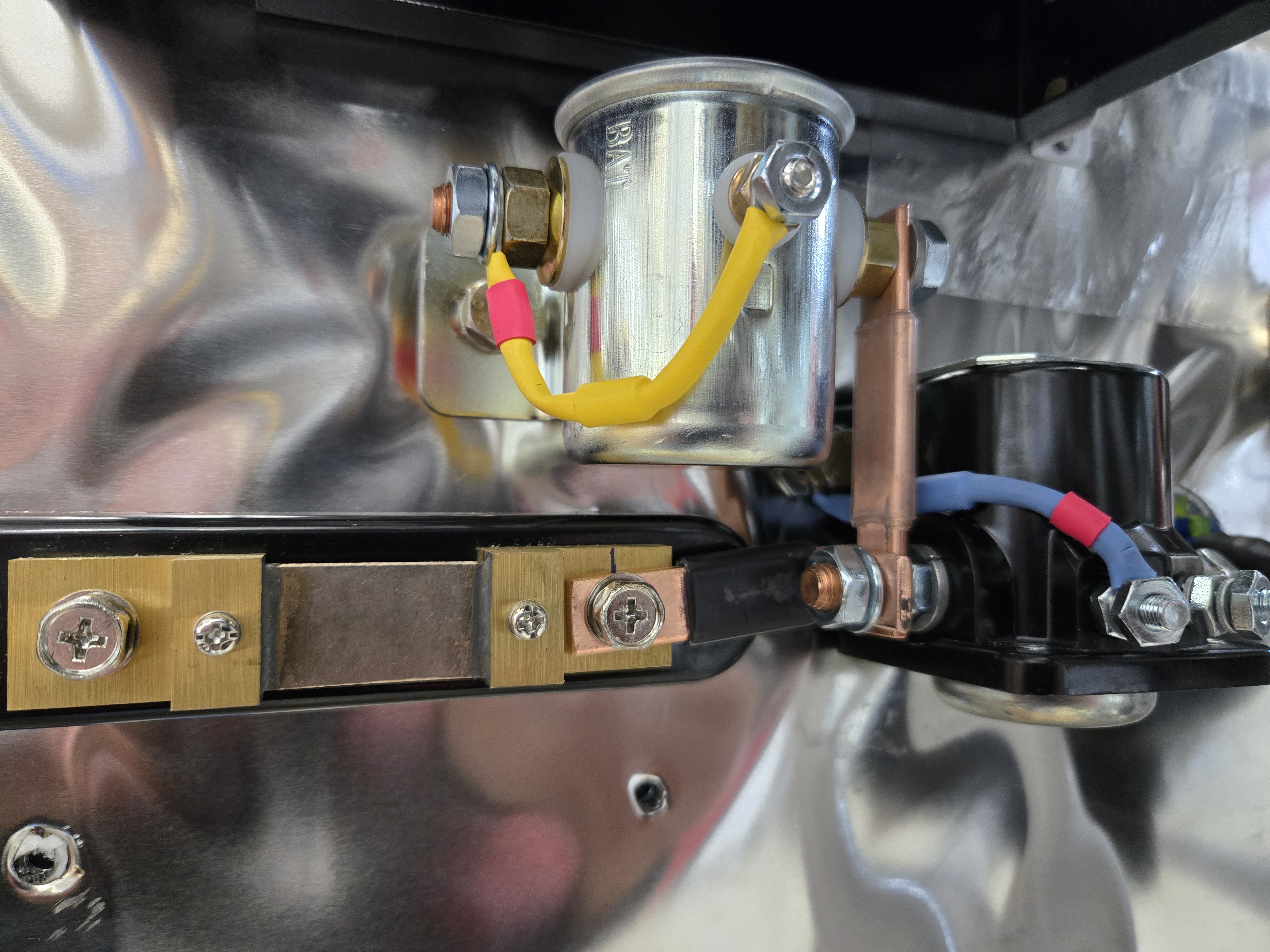
I haven't seen it in the instructions anywhere, but I know the master and starter relays need diodes to keep them from wearing out.  Van's is apparently saving money on wire with these diodes - they made the starter relay diode about as short as it possibly can be and still fit.  Even just 1/4" longer would have made a big difference in getting it put in place.


The brake fluid reservoir was next.  It was an easy fit, although I did end up taking it off and redoing it to add a couple of washers under the mount and make it stand further off the firewall.  Without the washers as spacers, the top part of the reservoir hit the firewall (the firewall has a bend and angles forward right about where the reservoir mounts).


I attached the sensor end of the oil pressure hose (the orange hose going horizontally across the firewall) and used two adel clamps to attach it to the firewall.  These premade hoses are really nice - the fire sleeve isn't the big, bulky sleeve that is often used.  It fits incredibly well and is a much cleaner installation.  I still haven't quite figured out where the oil pressure port is on the Titan.  I've been digging around online trying to find a diagram, but no luck so far.  Continental sent me basic operation instructions, but they are way behind Lycoming in terms of having documentation for the engine.  I suppose it's because they bought the company and it wasn't their own engine design.  I'll figure it out.  I just have to do more legwork to find the information.


Last up for today, I decided to start tackling the exhaust since it's one of the bigger pieces that everything else kind of has to fit around.  The learning curve forced me to do it all twice of course.  On my first attempt, I bolted the gaskets and first sections of the exhaust on all four cylinders.  I did it that way because the instructions made it sound like that was the right way.  Nope.  Only after all of that was torqued and done did I realize that there was no way to fit in the crossover tubes that connect the two opposing cylinder exhausts together.  It will all only fit if it's assembled loose, then the entire section is bolted to each exhaust port at the same time.

Everything but the last section of the tailpipes are in place.  The tailpipes are a little more involved because they have to be supported, yet still be able to move.  I'll tackle that on another day.

Tuesday, April 22, 2025

Misc - Firewall, Brakes, Static

The fuel tank attach bracket doesn't actually bolt to the fuel tank bracket like you'd think it would.  The hole in the bracket on the fuselage actually gets opened up so that the bolt can easily rip out in a crash.  This allows the wings to depart the fuselage if they hit something - this helps dissipate energy, as well as allows the fuel tanks to separate from the fuselage.  We had just temporarily bolted the brackets on when fitting the wings, so I removed them and cut out the slot, then bolted them back in place.


It's a little hard to see in the picture, but I pop riveted the insulation to the firewall using stainless steel rivets.  I spread sealant around the various penetrations as well (not shown in the picture).  I'll give the sealant a day to cure before I start taping over the joints with aluminum tape.  I only cut myself a half dozen times while putting rivets in.  You'd think I'd learn and wear gloves.


I'm a glutton for punishment, so I climbed up into the fuselage to hook up the static line in the tailcone.  I bolted the push fitting to the bracket I had riveted to the longeron.  This will support the static line as it runs to the center and up to the ADAHRS unit.


A long time ago I purchased steel braided brake hoses from Aircraft Specialty.  This is to replace the Van's approach, which is to use aluminum tubing down the leg and to the brake.  That approach works, but it's known for being prone to leaks over time after you've taken the brakes on and off a few times.  The braided lines are slightly longer than the gear leg to allow them to curl around a bit at the brake and allow for some flexing.  Since I'm pretty much past the point of having instructions from Van's, I looked up a few other builders to see how they attached the hose to the legs.  The consensus is that hose clamps don't really work because of the tapered leg.  As odd as it may seem, it sounds like most of the 11,000 RVs out there use electrical tape as the mounting method.  I cut some vinyl tubing into 2 inch pieces and slipped that over the brake line to add a little extra protection.  I don't love electrical tape, so instead I decided to use the self-fusing silicone tape, which sticks to itself really well and doesn't leave the nasty mess that electrical tape does after it's seen high temperatures.  I attached the lines at three places, then to give just a little extra layer of toughness around the silicone tape, I put a layer of Gorilla Tape on it as well.  All of this will set underneath the gear leg fairing.  I think it should work just fine, but is easy enough to redo 10 years down the road if need be.


To my surprise, I already received the oil filter bracket spacer from Continental!  I told them I didn't need it right away, but they overnighted it to me anyway.  This will definitely move the filter back far enough to make it easily accessed.  I'll attach this at some point before I run the engine, but I'm in no rush.