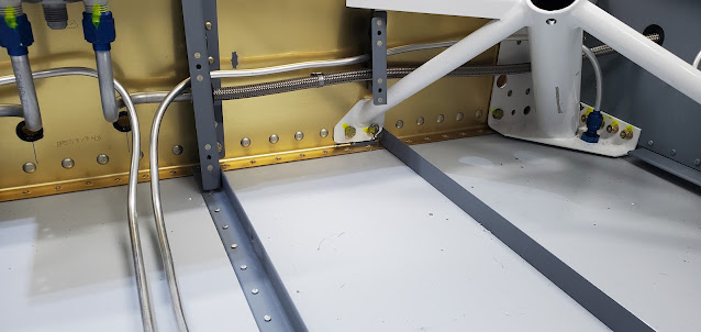
Time to run the brake lines! The brake line exits the fuselage at the base of the gear tower weldment. The fitting has a 45 degree angle on the exterior side to parallel the gear leg.
Running the 1/4" aluminum wasn't too bad, although it's virtually impossible to make it straight. It comes shipped in a coil, so by the time you uncoil it to start running it through the gear tower, then bend and twist it to get the entire length of it through the brackets, it's pretty wavy. For the left side, I flared the outside end first and then threaded the tube through to the center. That was a lot of tubing to push through (it goes to the center then runs all of the way to the firewall)! For the right side I started in the center and just pushed the smaller length to the outside, then flared the tubing in place.
I gave up trying to use the tubing bender to make any of the bends in the center section or at the firewall. It was easier to just put the spring bender on and bend them in place. It looks a lot better in person than in the pictures at least. Van's suggests sandwiching the center runs in between a couple of pieces of foam to stabilize them, but I think I'll probably just glue down a few zip tie mounts instead (I'll wrap each line with some silicone tape to pad them under the zip ties). The entire center tunnel of the floor ultimately gets a cover to hide everything.
At the firewall the lines exit from the center cover and pop up and over the firewall brace and over to the fittings that tie them into the actual brake pedal lines. The lines that go to the brakes are nice, teflon stainless braided lines.
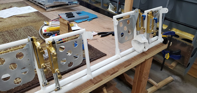
A few days ago I stopped working on the brake pedals because I was two bolts short. I ordered new bolts, which haven't arrived yet, but in the meantime I stumbled on a random bag of hardware and there were the bolts! I guess you can never have too many extras. After bolting the left pedals to the brake cylinders, the next step was to put all of the elbow fittings on the cylinders.
Most of the fittings are brass elbows that connect to the plastic brake lines, but the last fittings in the series (brake reservoir to right brake cylinders to left brake cylinders to brakes) are normal AN fittings that connect to the braided lines I installed on the firewall. I used Loctite 567 sealant on all of the fittings.
According to the drawings the AN fittings for the braided lines need to angle outwards instead of inwards like the other side. I will have to wait and see how this ends up working. I don't want the braided lines hanging over the pedals at all where I could accidentally catch them with my feet. My guess is there isn't enough room to angle them together towards the center though. I'll figure it out with some creative zip ties locations.
It seems kind of flimsy, but the connection through the firewall to the brake fluid reservoir is just a plastic T fitting. It's a lot like the pitot/static fittings that the plastic lines snap into. I suppose in reality there shouldn't be significant pressure going this direction to T, and it just needs to be leak free to keep the brake lines full.
Last up for the brake assembly was to run all of the plastic lines (I guess they're not really "plastic" - pretty tough stuff). These connect to the elbow fittings by inserting a brass ferrule in the line using heat and tightening it all up using a nut and compression ring. I drilled holes in the center hanger and put snap bushings in place. The lines from the right side bottom cylinder exit connect to the top of the left cylinder. The lines coming from the brake reservoir connect to the right side top elbows.
That's it for the brakes for now. They're pretty much ready to install in the fuselage and plumb. I'm going to wait to do that until I've got as much done around the firewall as I can though.
For a change of pace I decided to start building the landing lights. This portion of the lights was pretty straight forward - no soldering like there will be for the strobe and position lights.
Here's the finished product. These will fit in the leading edge of each wing. The light with the diffuser on it is the taxi light. The assembly can be wired so that all 4 lights are on for landing, but only the diffused light is on for taxiing to keep from blinding other pilots.


