Saturday, April 26, 2025

More Engine Hoses

I did a little more work on the electrical portion of the FWF.  I ordered some 1/8" copper bar and split it to about 1/2" wide chunks to make the connections between the solenoids and other power related bits and pieces.  The starter solenoid to amp shunt took a little zig zagging and step offsets to fit.  Yet another lesson in airplane building - if you have the room, go ahead and spread things out.  I tried to keep everything fairly close together because I wanted to leave room around the engine mount, but I probably should have given myself a little more space. 

I put a couple of layers of heat shrink over the middle of each bar, just to give a little protection from accidental arcs (although I don't actually think these will be carrying a load anytime I'm actually working near them).  Next up, I'll have to install the two fuses and run bars to each of them from the other side of the shunt.  I may have to use a heavy gauge wire for the bottom fuse holder.  It'll just depend if I can bend the bar enough to get over/around the top fuse holder.

The oil pressure line travels across the firewall and connects to a port just above the right PMag.  Unfortunately, when they put the hex head plug into the port, they rounded off the hex enough that getting it out turned into an hour long ordeal.  I was sweating bullets - the last thing I wanted was to strip the hex head even more and then have to suffer through using a bolt extractor on it.  It didn't help that they had thread sealant on it of course, so it was stuck stuck.  I eventually laid some scrap fiberfrax over the PMag and hit the case around the plug with the highest setting on my heat gun.  Once I got it nice and toasty the plug finally came loose!  The only thing I don't like about the location of this port is that it puts the oil pressure line really close to the wires going into the PMag.  I will have to keep an eye on it.  I may end up taking the 45 degree fitting out and redoing it so it exits a little more horizontally vs diving down towards the PMag.

I decided I should probably go ahead and add on the oil filter adapter spacer before things get too tight behind the engine.  This was pretty straight forward, minus one of the bolts that was difficult to get out because of access - I cut off a 7/16" wrench to make a stubby version that was about 2" long.  That gave me just enough room to work on the bolt and turn it little by little.  The spacer pushes the filter back far enough that it's now going to be super easy to get at it during oil changes.  Definitely a worthwhile modification.

Continental had already installed fittings for the oil cooler hoses, so I put those on, although I won't be able to finish them until I have the baffles installed (the oil cooler mounts to the back side of the rear baffle).


Friday, April 25, 2025

Firewall Devices and Exhaust

I got all of the overlapping seams of the stainless foil taped with aluminum tape.  The tape wouldn't stick to the areas that had fire sealant, so I had to cut around those areas.  I'll keep an eye on those spots over time to make sure they don't lift up, but I doubt they will.  The tape sticks extremely well on everything else, so I don't think it's going to budge.

My method for the wire penetrations is to have a split piece of firewall sleeve rolled and inserted into the metal tube, then a second portion of sleeve slipped over it all and clamped to the penetration tube.  A second clamp will be used to clamp the inner and outer material together after the wires are inserted.  I'll have to put some RTV or sealant over the fiber ends to keep them sealed.  I've seen people wrap silicone tape over the wire bundle and then over the end of the fire sleeve to make it gas tight as well.  That's on top of pumping a little fire sealant into the inside around the wire bundle.  I'll choose my method after I see how big the wire bundles end up being.

The manifold used for the fuel and oil pressure sensors had 3 ports on it, but since my manifold pressure sensor is a different type and aft of the firewall, I decided to cut off the third port.  If I ever need a 3rd port, I can always buy a new manifold and replace this one.  I can't think of what else I'd need it for though.  The reason I chopped off the third port is because it made it nearly impossible to get at a few rivets on the top firewall flange.  I inserted the fuel and oil pressure line fittings, put plugs on the unused sides of the manifold, then inserted the sensors.  I made sure to use Loctite thread sealer on all of these fittings.


I haven't seen it in the instructions anywhere, but I know the master and starter relays need diodes to keep them from wearing out.  Van's is apparently saving money on wire with these diodes - they made the starter relay diode about as short as it possibly can be and still fit.  Even just 1/4" longer would have made a big difference in getting it put in place.


The brake fluid reservoir was next.  It was an easy fit, although I did end up taking it off and redoing it to add a couple of washers under the mount and make it stand further off the firewall.  Without the washers as spacers, the top part of the reservoir hit the firewall (the firewall has a bend and angles forward right about where the reservoir mounts).


I attached the sensor end of the oil pressure hose (the orange hose going horizontally across the firewall) and used two adel clamps to attach it to the firewall.  These premade hoses are really nice - the fire sleeve isn't the big, bulky sleeve that is often used.  It fits incredibly well and is a much cleaner installation.  I still haven't quite figured out where the oil pressure port is on the Titan.  I've been digging around online trying to find a diagram, but no luck so far.  Continental sent me basic operation instructions, but they are way behind Lycoming in terms of having documentation for the engine.  I suppose it's because they bought the company and it wasn't their own engine design.  I'll figure it out.  I just have to do more legwork to find the information.


Last up for today, I decided to start tackling the exhaust since it's one of the bigger pieces that everything else kind of has to fit around.  The learning curve forced me to do it all twice of course.  On my first attempt, I bolted the gaskets and first sections of the exhaust on all four cylinders.  I did it that way because the instructions made it sound like that was the right way.  Nope.  Only after all of that was torqued and done did I realize that there was no way to fit in the crossover tubes that connect the two opposing cylinder exhausts together.  It will all only fit if it's assembled loose, then the entire section is bolted to each exhaust port at the same time.


Everything but the last section of the tailpipes are in place.  The tailpipes are a little more involved because they have to be supported, yet still be able to move.  I'll tackle that on another day.

Tuesday, April 22, 2025

Misc - Firewall, Brakes, Static

The fuel tank attach bracket doesn't actually bolt to the fuel tank bracket like you'd think it would.  The hole in the bracket on the fuselage actually gets opened up so that the bolt can easily rip out in a crash.  This allows the wings to depart the fuselage if they hit something - this helps dissipate energy, as well as allows the fuel tanks to separate from the fuselage.  We had just temporarily bolted the brackets on when fitting the wings, so I removed them and cut out the slot, then bolted them back in place.


It's a little hard to see in the picture, but I pop riveted the insulation to the firewall using stainless steel rivets.  I spread sealant around the various penetrations as well (not shown in the picture).  I'll give the sealant a day to cure before I start taping over the joints with aluminum tape.  I only cut myself a half dozen times while putting rivets in.  You'd think I'd learn and wear gloves.


I'm a glutton for punishment, so I climbed up into the fuselage to hook up the static line in the tailcone.  I bolted the push fitting to the bracket I had riveted to the longeron.  This will support the static line as it runs to the center and up to the ADAHRS unit.


A long time ago I purchased steel braided brake hoses from Aircraft Specialty.  This is to replace the Van's approach, which is to use aluminum tubing down the leg and to the brake.  That approach works, but it's known for being prone to leaks over time after you've taken the brakes on and off a few times.  The braided lines are slightly longer than the gear leg to allow them to curl around a bit at the brake and allow for some flexing.  Since I'm pretty much past the point of having instructions from Van's, I looked up a few other builders to see how they attached the hose to the legs.  The consensus is that hose clamps don't really work because of the tapered leg.  As odd as it may seem, it sounds like most of the 11,000 RVs out there use electrical tape as the mounting method.  I cut some vinyl tubing into 2 inch pieces and slipped that over the brake line to add a little extra protection.  I don't love electrical tape, so instead I decided to use the self-fusing silicone tape, which sticks to itself really well and doesn't leave the nasty mess that electrical tape does after it's seen high temperatures.  I attached the lines at three places, then to give just a little extra layer of toughness around the silicone tape, I put a layer of Gorilla Tape on it as well.  All of this will set underneath the gear leg fairing.  I think it should work just fine, but is easy enough to redo 10 years down the road if need be.


To my surprise, I already received the oil filter bracket spacer from Continental!  I told them I didn't need it right away, but they overnighted it to me anyway.  This will definitely move the filter back far enough to make it easily accessed.  I'll attach this at some point before I run the engine, but I'm in no rush.


Sunday, April 20, 2025

Engine & Gear Install

Another big milestone!  Time to put the plane on its gear and hang the engine!

I trimmed a few areas of the firewall insulation and foil to ensure that nothing would be pinched underneath the engine mount points. Back when I had test fit the mount and drilled all of the firewall holes, I noticed that the lower outer mounting points were not in the same plane as the rest of them.  That's apparently not all that uncommon.  To take up that gap, we placed a 1/16" thick washer under each lower outer mount point.  With those in place, we put the bolts in and torqued everything down.

I don't have a picture of it specifically, but before we put the mount on, we installed a number of the firewall items, as well as cut the fiberfrax and foil for the recess.

The battery, solenoids, shunt, etc are mounted on top of the insulation, so they do their part in holding it all in place.  The fiberfrax compresses pretty well, so even though it starts out soft, you can still crank down the nuts and screws fairly solidly.  I still need to buy a few longer screws for the fuse holders, so those aren't in place yet.


After the mount was on, we chained it to the engine hoist and lifted the plane off of the rolling cart that has supported it up to this point.  All three gear went on relatively easily.  I put a light coat of grease inside the main gear tower, just as a protection against corrosion.  I've gotten so used to seeing the plane sitting close to the ground that it really seems tall now that it has legs!


Next up, the engine!  It was a bit of a struggle just to get the engine and hoist close enough together.  We tipped the crate up and slide the hoist underneath, which got us close enough that we could then lift the engine and swing it all underneath the lift.  We eyeballed the chains and got it set to what we thought would be a level position.  If we had it to do over again, I would have actually tilted it back a tiny bit to help with alignment, but it worked okay as-is.


The install wasn't easy, but it also wasn't hard.  It's just very sensitive to the slightest off angle.  We started by putting in the lower bolts and tightening them up completely.  Then we let the engine sag under it's own weight (plus the weight of both of us pulling it down), which opened up the top mounting points enough to slip in the top donuts.  The top two bolts took a bit of wiggling to get in place.  With the gear and engine on, she's beautiful!


I discovered one gotcha with the engine install - the Titan comes with a 90 degree oil filter attachment, which allows the filter to more easily be accessed.  Unfortunately, the attachment put the filter right under one of the mount arms.  It was so tight that before I noticed it, we had crushed a small corner of the filter.  I shot off a couple of emails to other builders who I know have Titans, and they all said it worked fine for them.  After one sent me a picture, it was obvious that there is a big spacer that can be inserted on the attachment that pushes the filter a few inches aft.  I sent an email to Continental asking about it, and they responded with an apology, saying they must have forgotten to install the spacer.  I'm guessing they don't always put it on the engines, and they may just not have tracked the fact that this engine was intended for an RV9A, which obviously needs it.  They were great about it though, and said they'd ship me the part right away.

Friday, April 18, 2025

Initial Wing Fitting

The day for the wing fitting finally arrived!  Dad and I reorganized the garage and maneuvered the fuselage around to the middle to give enough room to put both wings on at the same time.  We strategically placed a few storage bins and blankets underneath each wing and tail to help take some of the weight while we were trying to insert them into the fuselage.

Before we worked on inserting the wing spars to the spar carry through we did our best to level the fuselage.  I was a little nervous about how the wing spar would fit into the fuselage.  There have been a lot of stories online of people who didn't quite get the space correct for the spar carry through area and had to do a lot of unriveting in order to get the spars in.  I was extremely happy to find that the spars slid right in with very little coaxing!  Dad lifted and wiggled the ends of the wings while I guided the spars into position and inserted the temporary bolts.  The rear spar attach gave us a little trouble at first, but we found that we just had to get the fore/aft angle of the wing right to get the rear spar to slide into place.

With the wings in place, the next step was to take a number of measurements to ensure that the positions were equal and within spec.  We measured from the wingtip to the center of the tail - the initial measurement was about 3/16" different from side to side.  A few small taps of the wingtip moved the left wing back enough that the measurements between both sides were almost dead on.  If I remember right, the final difference was less than 1/16".

I don't have a picture of it, but the next job was to check the forward sweep of the wings.  We dropped a plumb bob down from the leading edge at each wingtip and pull a string line between them.  Then we moved each plumb bob to the inside leading edge to see where they landed on the string line.  There was a difference of about 1/4" on the left and a little less than that on the right.  A little tweaking and we got the line to be right on.  With that done, we checked the wingtip to center tail measurement again to be sure it was still good, which it was.

I have to admit, it was pretty cool to finally see the plane with wings!

Surprise surprise, one more measurement!  Following the instructions, we created a block out of a piece of aluminum angle and added some wood and tape to it until we hit the exact size called for.  Then we placed that block on the rear spar line and put a level between it and the front spar.  It needs to be level, and it was right on the money.

With all of the measurements accounted for, it was time to drill the rear spar attach point to lock everything in place.  The edge distance on this part is very tight - to allow for the correct edge distance there is really only one center point that will work.  I used a block of wood as a drill guide to ensure I got the hole perpendicular.

Next up was the front fuel tank attach brackets.  We bent the brackets a couple of degrees (easier said than done) so they would match the angle of the fuselage and still set against the fuel tank bracket.  Similar to the rear spar, these brackets have a pretty small window for edge distance. I drew a little box that gave me the 1/2" edge distance and drilled the bolt hole.


I completely neglected to get pictures of the next couple of tasks, mostly because I was laying on my back under the wings to fit and drill the wing root fairings.  After that, with Perry's help we started fitting the flaps.  We put the flaps on and eyeballed where the pushrod would go through the fuselage to the flap control arm.  I can't say that I loved drilling a big hole in a perfectly good fuselage!  I got the final oblong hole where it seemed correct, even though we didn't set the final length of the pushrods.  I'm waiting on some replacement pushrod bearings before I do that.  I don't love Van's design that doesn't allow for a way to trap the bearing if it were to ever fail.  I ordered some normal pushrod bearings and bolts, and I'll set the flap movement down the road when I final install the wings and control surfaces.


Monday, April 14, 2025

Firewall Insulation / Flesh Shredder

I'm taking a step back in time to try to get caught up on entries for all of the work that's happened over the last week.  This is the last day I worked on the plane before Dad arrived.  I really wanted to get the firewall insulation to a point where it wouldn't hold us up if we were to work fast enough that we could get the engine hung.

Using my template, I cut out the fiberfrax, and as best as I could, I punched holes at (ok, near) the locations for the penetrations.  The fiberfrax and stainless foil only came in 2' widths, so I had to get a little extra of each to go all of the way to the top of the firewall.  My seam, which will allow for outgassing of the fiberfrax in the event of a fire, is about 8" or so from the top of the firewall.  Once the fiberfrax was fit and gave me some confidence that the size was right, I moved on to the .005" stainless. Cutting the outside lines of the stainless was easy enough with shop scissors, but the interior holes weren't as easy.  Regardless of which tool I used, the holes just couldn't be cut smoothly.  Tin snips worked the best though.

I laid the fiberfrax on the firewall and held it in place while I put on the stainless.  I used a couple of rare earth magnets to help hold it all together.  That's where I stopped before Dad got here to help.  The picture below was taken a few days later when I had laid out and drilled holes for the stainless pop rivets.  While all edges will get fire sealant (as much for protecting unsuspecting fingers from being sliced off as for fire protection), the foil and fiberfrax need to be held on mechanically as well.  In the very unlikely case of a fire, the sealant expands and chars, so it will not hold the insulation in place all on its own after it's heated to that extreme.

This part of the plane has by far the most blood given in sacrifice of the build.  That stainless foil is essentially razor blade material, and it lives up that.  I don't have a specific picture of it, but we spent a considerable amount of time figuring out the origami required to wrap the firewall recess too.


Saturday, April 12, 2025

Fuel Tank Bracket & Finishing Up Firewall Prep

Last week I read up on the process for fitting the wings, since that'll be one of the big tasks to do next week.  In doing so, I realized that I had never made the fuel tank attach brackets that mount to the fuselage.  These are very similar to the brackets that are attached to the fuel tank itself.  Unfortunately I didn't have enough 3/16" thick aluminum angle to make the brackets.  I'm sure I had enough material originally, but over the years used it up remaking some other parts or something.  Thankfully there's an onlinemetals.com location in Seattle, so I was able to buy a 12" piece of the 2 1/2" x 2 1/2" angle without paying insane shipping costs from Aircraft Spruce or Van's.  I was surprised that onlinemetals actually carries the right structural angle (vs architectural angle) in the right composition.  The structural stuff has the radiused angle vs just a 90 degree angle with no radius.

The brackets aren't complicated to make, but they take a while just because of the thickness of the material.  Even though aluminum is pretty easy to work with, when it's 3/16" thick, it takes a while to cut and shape it.  That's all I can do on the brackets for now.  They will be match drilled to the fuselage and fuel tank bracket once the wing is in place.


I'm still chipping away at the firewall.  Today I fixed a problem that the plans caused a year or so ago.  When I first built the firewall, the drawings showed to make a doubler for the aux fuel pump that sets below the fuel line fitting.  I dutifully followed the instructions, riveting the doubler and drilling the two big bolt holes.  Sometime down the road I discovered that this was only for the fuel pump used for a carbureted engine.  I hadn't gotten to the point of working on my boost pump setup yet, so I didn't know there was a different setup for an injected engine.  Now I've learned that virtually all of Van's instructions are for the carbureted engine.  I don't think the injected engine was a common choice 25 years ago when the 9 came out.  So now I have two empty bolt holes in the firewall.  I went ahead and riveted a couple of nutplates in place.  I will wait to fill the holes with bolts until later.  Maybe I'll figure out a use for some clamps in that location or something.


Yesterday I put the ground block in place, but I don't think I took a picture.  It's a brass, forest of tabs on the aft side of the firewall.  There is a big, brass bolt that extends through the firewall - the battery ground and engine ground will attach here.  I will actually use very few tabs for grounds, unlike a typical wiring scenario.  For the most part, the ACM takes care of the device grounding internally, so the ACM only needs one big wire going to the airframe ground.  There are a few grounds that the ACM doesn't handle that I'll have to run though, and for anything (like the heated seats) that doesn't go through the ACM, I'll use the forest of tabs.


I think most of the firewall penetrations are sorted out, aside from the control cables (throttle, mixture, alternate air and oil cooler shutter).  I made a poster board template of the firewall and cut out the locations of all of the penetrations.  Some of these spots will have the insulation removed completely because the item is already mounted directly to the firewall, and for other spots I will punch small holes for bolts that will mount objects on top of the insulation.  I'll use the template to cut out the fiberfrax and stainless overlay - hopefully accurately!


I've been putting off riveting the firewall recess in place just because it's handy to have a big, open hole to reach through.  I'm sure I'll regret it at some point, but I think now I'm at the point where there's not really much else to do that I can't easily do just reaching over the top.  So riveting it is!  The recess is full of seams and has gaping holes in the corners, so I ran a bead of sealant under the outside edge and then filled the corners after it was riveted together.  Sticky stuff!

Thursday, April 10, 2025

Firewall Doublers

I plan on initially just having a single alternator, but once I set the plane up for IFR (or start doing a lot of cross country flying), I will probably want to add a backup alternator.  I would like that to be a plug and play event vs a big makeover of wiring and firewall work.  I emailed back and forth with one of the tech support folks at B&C, which is a well regarded alternator and electronics vendor.  They were really helpful in explaining the easiest way to set up a dual alternator system using their internally regulated units (vs externally regulated, meaning fewer boxes and less wiring).  I figured out that if I run wiring for a standby alternator switch and put in the nutplates for a second ANL fuse mount, adding the second alternator should be as easy as putting it in place on the accessory pad and wiring it up.

I made a doubler to mount the amp shunt and existing ANL fuse to using AN3 screws.  The B+ lead of the primary alternator will go to the ANL 60 fuse, which will then connect to the shunt.  When I add the standby alternator (likely a 40 amp, since that's what B&C has for an internally regulated standby unit, even though it's far larger than I'd need for a backup), I'll add a second ANL 40 fuse and the standby B+ lead will go to it.  That ANL 40 fuse will then also attach to the shunt.

I offset the mounting location for the two ANL fuses, just to make it easier to route the wires to the shunt without interfering with each other.  I probably should have made the doubler a little bigger so I could spread things out a little bit more, but I had already gotten it all drilled to the firewall by the time I figured out that a second ANL fuse would be necessary with the standby alternator.

This doubler attaches to the lower, right side firewall. One screw from the shunt attaches to a nutplate in the doubler, but the inboard mounting screw of the shunt uses a nutplate on the firewall stiffener.  I had the fuel fitting doubler done and just sitting there, so I grabbed it and prepped it to be riveted to the firewall.  The dimension on the plans won't work though - the top outside corner of the doubler interferes with the start solenoid mount.  I ground away a corner of the doubler and riveted it on.  After that, I put the washer doubler on the fuel fitting, added some fire sealant and torqued it down.

I attached the nutplates and riveted the doubler to the aft side of the firewall.  I also attached the fuel line to the fitting.  I torqued it down, but looking at the picture, realize I still need to add torque seal so I know it's been done.


Monday, April 7, 2025

Mains - Brakes

The fairing brackets on the main wheels bolt to the inside of the collar that the brake bracket also bolts to.  There is also a small fairing bracket that screws into the axle nut on the outside, but I won't put that in place until it's time to install the fairings.  The brakes attachment is a little strange - the main body doesn't actually mount solidly to anything.  The body has two pins that slide into the attach bracket and allow the body to move in and out.  With the body in place, I slid the outside shoe in and bolted it in place.  The sliding pins and the brake shoes are all that hold the whole assembly on the wheel.


Sunday, April 6, 2025

Firewall Holes & Nose Gear

One step closer to getting the firewall penetrations finished up!  I'm now at the point where there is no guidance by Van's regarding locations, so I've been sitting and staring and mulling over what will need to go through the firewall.

The manifold pressure sensor will connect to cylinder 3, so it'll go through the firewall on the upper right side.  Van's provides the kit for plumbing, but not the sensor itself (which I got from AFS along with all of my other engine sensors).  I held the brake fluid reservoir up to see where it would go, then just eyeballed where the fitting could go for the manifold pressure plumbing. I put a little fire silicone sealant under the fitting, even thought once the insulation and foil is on, I'll also surround the cutout with sealant.

After that was set in stone, I moved on to the right side pass through for wiring.  There are a lot of ways to accomplish this, but the most common is to use a flanged tube that extends through the firewall and gets wrapped in fire sleeve.  Then, another piece of fire sleeve is inserted into the tube, mostly to aid in sealing around the wires.  Once the wires are in place, fire sealant is pumped into the area to provide a gas tight seal.  The problem - this little kit of a flange and a small section of fire sleeve is $90! And I need two.  I know aviation is expensive, but that seems pretty ludicrous. 


Those crazy expensive tubes look awfully similar to a good ol' closet rod hanger.  Funny enough, when I searched on that on the forums, I found that a lot of people go the route of the rod hanger.  I found two stainless steel hangers on Amazon for $10.  Combine that with $20 of fire sleeve and a few hose clamps and I've got pretty much the exact same setup as the real deal for about $130 less.

I drilled a pilot hole in the firewall, then upsized it until my knock out punch would fit.  I bought a cheap punch set from Harbor freight.  It's made for conduit sizing, so it's a tiny bit off from what I needed for the tube.  I used a grinding stone in my die grinder to chew away the last 1/32" I needed to get the tube through.  Then I drilled matching bolt holes in the firewall.  I made a doubler to go on the forward side of the firewall and riveted it on.  I forgot to put sealant under the doubler when I riveted it down, so I slathered it on liberally once I was done.  Like with anything else that is permanently fixed to the firewall, it'll get another layer of sealant after the insulation and foil is cut around it.


The manifold pressure sensor AFS sent is nothing special.  It looks like it's probably an automotive setup.  I decided to mount it vertical instead of horizontal to get the intake tube higher than the level of the firewall fitting.  The instructions say to try to keep it so water can't run into the sensor.

Something I just randomly found out while I was digging through various websites and manuals is that the Pmags also use manifold pressure to help with their timing.  I will have to put a T in the manifold tubing by the sensor and run it back out the wire penetration to connect to the Pmags (it'll need a second T in the engine compartment since it'll have to split and go to both Pmags).


I repeated the whole process for the left side.  Of course it went twice as fast.


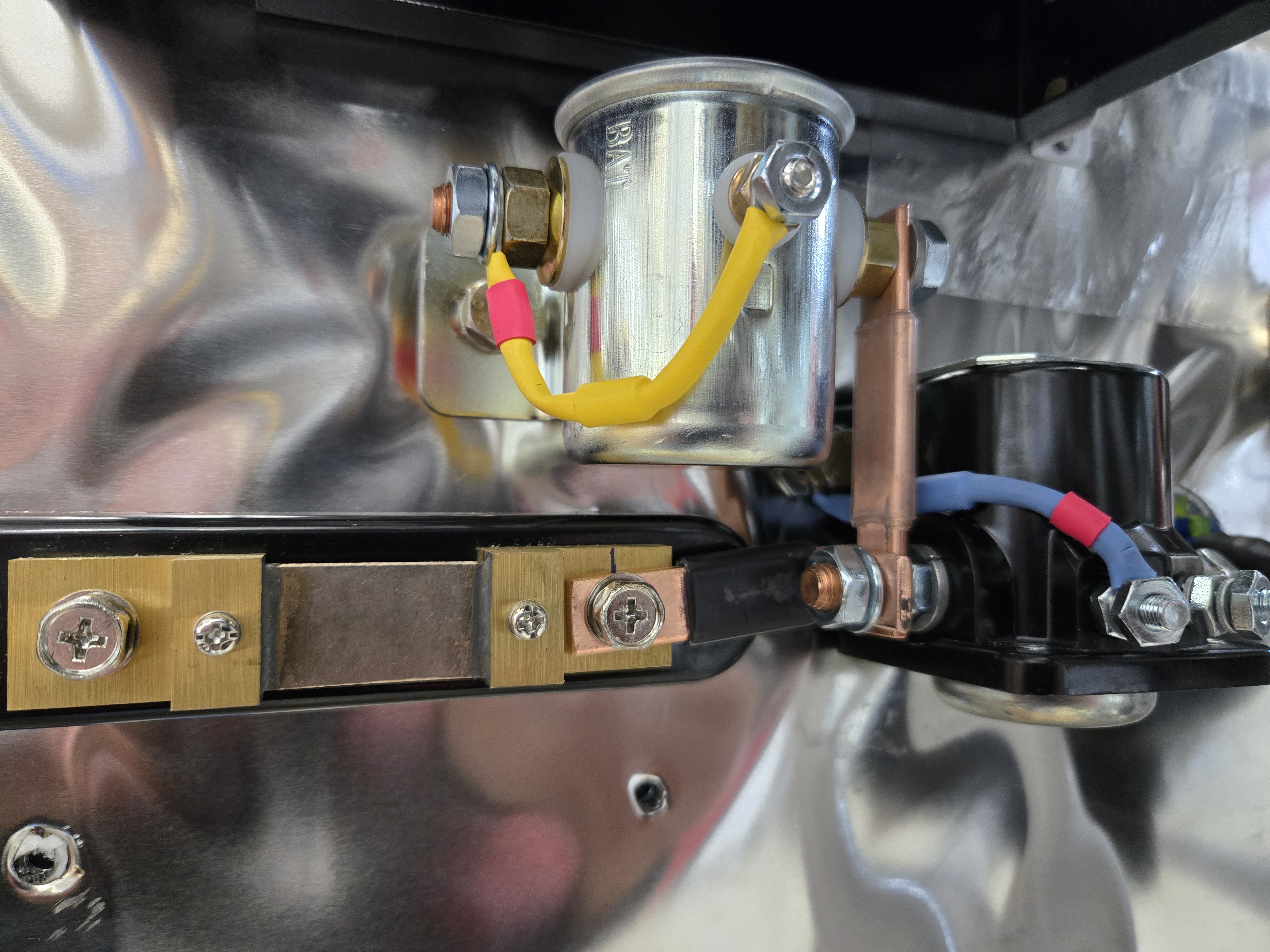
There are a couple of other mounts I need to sort out tomorrow - one mount for the AMP shunt and one for an ANL fuse.  The ANL fuse was a late addition that I decided on today.  Even though aviation alternators have over voltage protection, there's still some paths where a short or other electrical failure can fry downstream systems.  The ANL fuse is a 60 amp fuse that will be in between the alternator and everything else.  If the alternator truly implodes, I'll have one extra layer of protection.  Putting a $20 fuse in to protect many, many thousands of dollars of computers just seems like a no brainer.  I guess it's not something most people do (probably simply because it's not included in Dynon's standard engine wiring kit), but it was recommended in Bob Nuckoll's book "The Aeroelectric Connection."  That's basically the electrical bible for experimental aviation.  Apparently boats also use ANL fuses a lot, so I was able to find the exact fuse and mount sold by aviation suppliers on Amazon (for a fraction of the price of course).  

Moving on from the firewall for the day...

The parts I painted yesterday were cured enough to handle, so I went back to working on the wheels.  I riveted nutplates onto the nose wheel fairing brackets.  These brackets will be what the fairings screw onto.  The brackets are attached underneath the axle bolt washer and nut (there are two smaller washers that provide thickness spacers for the brackets), and the front is screwed to the fork using big allen bolts and lock nuts.


The gear leg is drilled through at the top to attach a collar with a bolt.  This collar acts as the rotation limiter by bumping up against allen bolts that are screwed into the top of the fork. Simple and effective.

I pumped the fork full of grease and then worked on setting the break out force of the wheel.  There are two huge "spring" washers on the bottom of the gear leg, then a nut.  I slowly tightened up the nut and moved the wheel back and forth until the breakout force was 22 lbs.