Today I got a lot of "education" done, but not much actual work. I got my flaring tool the other day, so figured I'd hammer out the tank plumbing today and be ready to seal the left tank in the next day or two. Instead, I spent a few hours dialing in the flaring tool and a few hours researching torque ranges for fittings (it took hours because no reference seems to agree with the others).
The Rigid flaring tool works great, although I did have to modify how it is supposed to be used because of how soft the aluminum tubing is. The aluminum tubing Van's supplies is 3003 aluminum, which is very soft, at least relative to something like 5052, which is more commonly used in aircraft. For something as ho hum as a fuel vent line that will see no pressure or stress, the 3003 is actually nice though, because it's easily bent and worked through the ribs of the tank. The gotcha is that it's really easy to over flare using the Rigid tool. The tool has a clutch built it that is disengages the pressure at the "correct" amount of flare. I'm sure it works great for stainless steel or copper, but it's too aggressive for the 3003. It took me a lot of playing around to figure out just how many turns of the handle made the perfect flare (4.25). This was a couple of turns before the clutch would have normally released. After a bunch of experimenting, I was able to get pretty consistent flares though. Like anything, prep was key - cut the tubing, square it off with a file or on the sander (the tubing cutter has an angle to the cut), deburr, then lubricate with oil/Boelubeto help the flare die move smoothly.
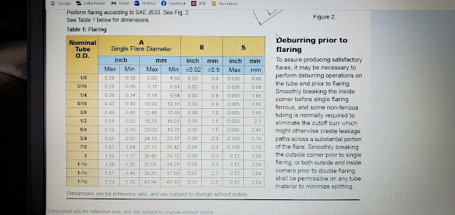
I found someone had posted a nice chart on VAF to show what the flare diameter should be based on tubing size.
Once I had flaring figured out, I flared the end of the roll of aluminum tubing that comes in the kit and then started figuring out how much to cut off for the vent line. In the end I had to insert then pull the tube out 3 or 4 times and cut off more and more until I got it right. The only reason it was a little iffy and not a straight forward measurement was because of the angles that are required in the inboard bay where it attaches to the bulkhead union fitting.


