Saturday, September 30, 2023

Steps (2) & Baggage Floor

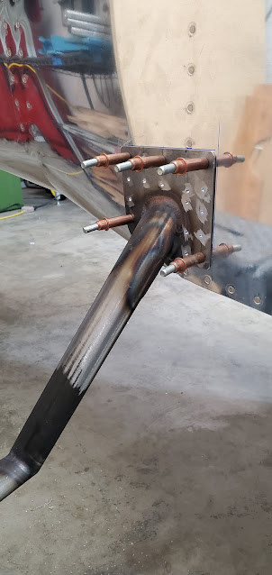
I let the proseal set up a bit before riveting the steps. The finished product is a bit messy looking just because I used acetone to remove the excess proseal (which also takes off some primer), but the entire thing will be cleaned of the existing primer and scuffed before final painting anyway.  It never ceases to amaze me how solid these parts become when assembled. 


With the steps in, I can start moving to the side panels and flooring.  The aft baggage side panel gets permanently mounted, whereas the front one is removable (to allow for access to the flap controls).  I waffled back and forth about whether to go ahead and start installing stuff like this or if I should paint the interior first.  I decided to install anything that's permanently mounted, then down the road I'll paint the entire interior at once.  Because I plan on putting in an interior (carpet and side panels), there won't really be that many areas that need paint anyway.  The seat back support and baggage area is about it.


The baggage floor was next.  I put it in place and match drilled everything.  Most of the floor is permanently mounted (with pop rivets, since there is no access to buck rivets), but the center tunnel gets a separate cover that is screwed down using nutplates.  This is where the elevator control tube goes through, as well as room for wire runs.


After rain for the majority of the week, today had a little sunshine, so I jumped at the chance for priming. I didn't want to just prime the baggage floor pieces, so I prepped the seating area flooring as well and primed it all. 


The next step is to install the baggage flooring for good. The plans have two holes in the center tunnel for wiring, but with how avionics and electronics have changed over the last 20 years, I'm not sure that those two holes will be enough.  Because the floors are installed permanently, I want to future-proof everything and make it as easy as possible to pull additional wires down the road.  I spent hours looking for information online about where additional holes could be drilled in the fore and aft bulkheads.  In the end, I drilled 3/4" holes in the outboard bays to accept some wiring conduit.  I may have to drill holes in the 904 wing spar carry through as well  (the big gold bulkhead in front of the seats) to run wires forward to the panel, but I'm not going to do that until I know for sure.  Van's does have templates for where those holes can be drilled, but I'd rather not do that unless I know I need them.  


Sunday, September 24, 2023

Steps

A while back while the fuselage was still upside down and I was riveting ribs and supports in the baggage area, I neglected to put a small 3" aluminum strip in place that ties the corner rib to the baggage bulkhead.  It just lays on top of the corner rib and essentially extends it an inch or so, allowing it to be riveted to the bulkhead flange.  Since my riveting partner was out, I had to figure out a way to back rivet the 3 rivets per side by myself.  It turns out a floor jack holds a back rivet bar nice and solid.


You can see the strip in the picture below - barely noticeable, but the piece that is on top of the angled corner rib on the upper left corner of the picture.

Next it was back to the steps.  The 3/16" bit for my right angle drill arrived today, so I was able to drill the plastic block into the ribs, as well as drill through the step tube itself.  The block gets bolted to the rib, and once the step is prepped and ready for riveting, it also gets a long bolt through the tube.


The instructions just say to prime the steps, but since it's raw steel against aluminum, I want a thin layer of proseal between them as well.  I mixed up a small batch of the goop and spread it as thinly as I could.  I clecoed through every hole to hold it as snug as possible while it dries a little.  I'm taking a lesson from my fuel tank building days and choosing to wait at least 24 hours before I pull clecos and rivet.  It's just much less messy that way.


Saturday, September 23, 2023

Forward Gusset & Static System

I received the replacement forward firewall gusset from Van's.  I went through the same process as I had before to lay out the holes, but the big difference was the fact that I had already drilled a few holes in the longeron with the original gusset.  That's when I had discovered the issue with the edge distance on the engine mount bracket when using the measurements from Van's.  So this time I cheated the holes over as far as possible to use every last bit of space on the engine mount bracket.  Because there were already a couple of holes drilled in the longeron, I had to match drill those to the gusset from underneath, which was easier said than done.


In the end, everything worked out.  The three rivets in the original hole locations (2 in front and 1 aft) make me twitch a little because it looks like a drunk laid out the rivet line, but I'll get over it.  The important thing is that I gave both the longeron and engine mount bracket as much edge distance as physically possible for these parts.


I may kick myself later, but for some reason the plans have you wait to install the aft bulkhead until the top skins are on.  Given that I already match drilled the skins to the bulkhead, I don't see any reason to wait to rivet the bulkhead to the aft deck.  It'll be far easier to rivet it now while I have easy access, rather than deal with it when the top skin is in the way.  I think I explained this before, but my aft deck is slightly off center, so the pre-punched holes in the forward flange don't match up perfectly to the holes in the bulkhead.  Van's said that it's no big deal, and to just drill new holes in between the pre-punched ones.  Once I had drilled those, I didn't like leaving the pre-punched holes empty, purely because someday if I sell the plane it would raise eyebrows to see a bunch of empty holes, and people would wonder if there were missing rivets.  So purely for aesthetic reasons, I went ahead and put rivets in all of the holes (the new holes are the structural ones - the pre-punched ones are not since the holes became oblong when match drilling them due to the offset).


The proseal attaching the static ports is cured now, so I started playing around with how I would set up the static lines.  The left and right ports need to be connected, then a single line taken forward to the ADAHRS box, which I'll probably mounted between the J stringers behind the baggage area.  I used 90 degree elbows at the ports, then a T fitting on the left side.  What I need to figure out still is how to stabilize that T fitting.  It has a hole to mount it using a bolt, but as luck would have it, it is right where one of the bolts holding the seat belt anchors goes.  At first I just fabricated a piece of angle, but then realized there would be no room for both the seatbelt anchor bolt and the T fitting bolt.  I'll have to keep thinking about that.  I won't attach any of this permanently until the top skins are on anyway, because it would all get in the way of bucking the skin rivets.


There are very few instructions for the build anymore (the static stuff isn't even called out in the plans, at least not that I've seen yet - maybe later?), but I figured I should have some supports for the tubing as it goes forward.  I drilled out two rivets that were in place to hold the side skins to the longeron until the top skins are on.  I fabricated two little angle brackets and riveted them in those locations.  The brackets have a 3/8" hole and a snap bushing.  I'll run the tubing forward and through a similar hole in the next bulkhead, then to the ADAHRS box.


I took a breather and thought about that T fitting mount - I decided that the fitting really didn't need to be parallel to the skin.  The tubing has to go from the T to underneath the longeron, so it's actually better if the T has a bit of an angle to it to help with that transition.  That means that the bolt hole in the fitting can be angled backwards - hopefully enough to help clear the seatbelt anchor bolt.  It's hard to explain.  I took a piece of paper and did some origami to figure out how to clear as much space for the anchor bolt/nut as possible and still have a spot to bolt the T fitting.  This is what I came up with:


I cut out the shape, drilled the two bolt holes and bolted the T fitting to the mount.  Getting to the seatbelt anchor nut underneath the longeron is still going to be tight, but I think it's doable now.  This might be overkill, since I've seen people use these T fittings without any support at all, but it seems like a solid mount will lessen the chance of a leak since the vertical tube from the other side comes in at a bit of an angle.  The mount will position the fitting vs forcing the tubing to position the fitting by itself.


Sunday, September 17, 2023

Static Port

I don't have much to show for progress today.  I was ready to do the final drilling of the steps to the inside support block and baggage ribs, but it turned out that the drill bit I had was too long to fit.  Because of the tight quarters, I have to use a right angle drill, so I had purchased a 3/16" hex bit that would work in my right angle drill attachment (the one that can just be chucked into another drill).  I thought I'd go that route because the bits are so much easier to get than the pneumatic right angle bits that are threaded.  I received the hex bit today, only to realize that I can't fit it and the angle drill attachment in between the baggage ribs.  So instead of finishing up the steps today, I broke down and found a single 3/16" threaded bit on ebay.  I tried other industrial supply shops, but none of them would sell single bits, and if they did, they wouldn't ship them unless I had at least a $50 order.

I just clamped  the steps in place and moved on to a few odds and ends.  I riveted the F-787 stiffener in place, as well as the little angle bracket at the aft side that connects it to that bulkhead.  Of course, after I had done that I realized that by doing this, one of the top skin to bulkhead rivets will be impossible to buck.  I could drill out the rivets from the angle bracket, but putting those in after the skin would be an absolute nightmare as well.  So I think I'll probably just leave it and use a single pop rivet in that location instead (Van's approves the use of certain pop rivets in replacement of 3- rivets).


Since I'm kind of twiddling me thumbs until I get the drill bit for the steps, I decided to bite the bullet and drill holes for the static source.  I'm not a big fan of Van's approach for this, so I'm using a third party setup that I purchased.  It's a kit that includes all of the plumbing and fixtures for the pitot/static runs.  I used the standard Van's location (one on each side about 2/3 back the tailcone), but did move the hole about a 1/2" forward so that the fixture would clear the bulkhead flange on the inside.  While Van's approach to making a static port is to use a pop rivet with the shank popped out, this setup is a nicely machined port that lays flat on the inside of the skin and just protrudes a small amount on the outside.


I could rivet the port in place, but that seems like overkill.  The company says proseal on the inside surface works just as well, so that's what I ended up doing.  Once the proseal cures I will start putting the fittings and static lines in place.


Saturday, September 16, 2023

Fuse Gusset & Steps

I decided to order a new left side forward fuselage gusset since the holes in the previous one didn't provide enough edge distance for the engine mount bracket.  I still have to laugh at the fact that a replacement part like this on a certified plane would probably cost a few hundred bucks.  It cost me $7 plus another few bucks in shipping.

I went ahead and riveted the right gusset into place.  I was able to do all but a couple of rivets with my squeezer.


There's really no way to get standard edge distances on the engine mount bracket, but Van's says this is the norm and not to worry about it.  Edge distance is to keep material from cracking and tearing out, so I suppose it makes sense that steel would have different requirements than aluminum.  The other holes in the bracket will stay open until the top skin by the firewall gets put on.


More random stuff - I decided to go ahead and just use the spray can primer on the remaining parts that will go in the tailcone under the top skin.  As much as I prefer "real" primer, the convenience of the can is very tempting when there are only a few parts to do.


Steps are an option on the 9A, and I decided to put one on each side.  The instructions that come with the steps are very old (hand drawn plans that cover as far back as the RV6).  The steps have a plate that mates to the side skin and a tube that extends inside underneath the baggage floor, where it fits into a plastic block that is bolted to one of the baggage ribs.

I started with the left side.  The first thing I had to do was open up the 1 1/2" hole I had drilled in the side skins a while ago.  That's the right size hole for the tube, but it doesn't allow enough room for the weld that attaches the tube to the plate.  I finally broke down and bought a Dremel the other day - I wish I had bought that eons ago.  It made enlarging the hole so much easier than my previous method of using files.

I laid out the rivet locations on the plate.  One of the rivet lines (2nd from the front) has to line up with the F-724 bulkhead inside the baggage area.  I moved that line of rivets over about 1/4" from what the plans show so that it would land in the middle of the 724 flange, as well as not hit the external weld of the step.  The one gotcha with having to line up with an existing row of rivets is that the rivets in the step plate can't land on top of other rivets or cause edge distance issues with any of them.  I had to move two rivet locations to make sure they'd be in okay places.  I rounded off the corners of the plate and trimmed the lower aft corner off.  This is the area where the fuselage has a big curve and transitions towards the tailcone.  I got lucky on this step - normally the aft side of the plate also has to be "massaged" with a hammer to make it lay flat on the skin.  I only had to do a little bit of pounding on the aft bottom corner to help it curve with the skin.


I drilled the holes in the plate using the drill press, then clamped the tube and the plastic block to the baggage rib to stabilize it all and drilled the matching holes into the skin.


The plastic blocks need three bolt holes drilled into them - 2 to attach it to the rib and one that goes through the step tube itself.


The right side step ended up being a lot more fiddly than the left side.  For some reason it just didn't want to lay against the skin.  I ended up having to pound a pretty significant curve into the lower aft corner, but after 100 trips back and for to the vice, I got it to match the skin.


The steps are steel, so definitely need primer to keep them from rusting over the next few years before the plane is painted.  Since I'll eventually want to prime them with whatever high quality primer I used with the exterior paint, I didn't spend time scuffing the metal.  When it comes time to paint the plane, I'll wipe this primer off the steps (it's the spray can stuff, so acetone takes it right off) and just refinish them with the good stuff.  This is the approach I've taken on all of the parts that hang in the breeze and will get hit with paint, like the flap and aileron brackets.

I'll throw a little primer on the skins before I attach the steps.  I've seen quite a few RVs with rust that starts at where the step meets the skin.  I assume it's because of the dissimilar metals.  It's probably not absolutely necessary with both surfaces primed, but I think I'll put a thin layer of proseal under the plate before I rivet it on.  I think having that in between the metals will go a long way to keeping the rust from starting.


Saturday, September 9, 2023

Tailcone Skins & Bulkheads

I neglected to get a picture of it in place while I was fitting it, but I started out today with a nice, easy task - riveting together the elevator bellcrank.  It's a pretty straight forward part, with a bearing, long bolt, and a couple of aluminum spacers I made to keep it centered and in the right place.  I pulled it back out for now.  It'll go back in down the road when I start rigging controls.


Previously I had gone through the effort to square up all of the flanges on the tailcone bulkheads, because that's what you do. Past me didn't think about the fact that the whole tailcone gets smaller towards the rear, so of course the flanges shouldn't actually be at 90 degrees to the rest of the bulkhead.  Duh.  I laid a level across the bulkheads to get an idea of what the angle should be, and then bent the flanges upwards to hit an angle that would put them close to that of the skin.  If you don't do that, when you rivet them together, the space will close up just fine, but you will get a divot in the skin as the area around the rivet sucks down towards the underlying flange that isn't laying up against the skin.


Just like for the side skins, the top skins also get two J channels as stiffeners.  I had made these back when I made the ones for the side skins.  I just taped the fore and aft ends to the bulkheads to keep them in place until the skins went on.


I put the rear top skin on first and final size reamed all of the holes (except drilling all of the holes through the J channel - I did that after the other top skin was on as well).


The bulkheads are shockingly floppy until they are locked in place by the skins.  The middle and front bulkhead need a gusset that ties them to the longeron as well.  The problem is, because the bulkheads can wiggle around so much, you can't put the gusset in place and drill it until you first have the skins on to ensure the bulkhead is sitting in the right position.  It was a lot of awkward contorting and reaching to cleco the gussets to the bulkheads, then push them into place so they were parallel to the longeron and clamp them for later.  The picture below is of the front gusset after I took the skin off just so you can see what they are.


With the rear skin on, I put the gussets in place on each side, rotated them into position over the longeron (because the bulkhead web flexes and doesn't naturally sit at the right angle), and clamped them.


The front top skin overlaps the rear one, and extends up the sides of the baggage area.


I had drawn a line down the center of the J channels so I could reference it and make sure not to make things too wonky when match drilling holes through the skin (the skin has pre-punched holes, but the channels don't).  At the front half of the tailcone there is also a stiffener web that goes from the front bulkhead to the second bulkhead and connects with a small angle bracket I made.  I final size drilled it to the top skin as well.


The very rear of the plane by the aft deck (where the horizontal stabilizer gets mounted) gets another bulkhead that closes out the back.  I had to go a little overboard with the rivet holes here.  When I had put the aft deck on, nothing in the instructions said to make sure that it was perfectly centered on the longerons from side to side.  It's pretty close, but not perfect.  That would have been fine, except the lower row of rivets in the rear bulkhead that attach it to the vertical flange on the bulkhead came pre-punched, meaning they only match up if the aft deck is exactly centered.  I'm off center by about 1/16", which doesn't seem like much, but that's half of a hole.  I asked Van's, who said just to put the bulkhead in place and drill new holes in between the pre-punched ones.  I'll only have to put rivets in the new holes for it to be structurally sound, but I think I'll probably fill all of the holes just so there's no question down the road about why I have what looks like missing rivets.


After all of the skins were drilled, I pulled them back off.  I'll leave them off for a while, since it'll be a whole lot easier to work in the rear without them in place.  I drilled and riveted the rear two bulkhead gussets.  


I started to rivet the front two gussets to the 706 bulkhead (this is the bulkhead that is at the rear of the baggage area), but realized I need to figure out how to dimple them first. They just get universal head rivets to attach them to the longerons, but the rivets that attach them to the bulkhead are flat head rivets since the rear baggage panel mates up flat against the front side of the bulkhead.  Normally dimpling is no big deal, but none of my dies for these 4- rivets will fit in the space.  I'll either have to see if someone makes a small diameter 4- die (like they do for 3- rivets) or just come up with a homemade die and use the hammer approach.


Friday, September 8, 2023

Fwd Fuselage Gusset (2)

I did my typical two steps forward one step backward tonight, although there's not much I could have done to keep it from happening.  I put the gusset in place and started to drill holes through the longeron and into the engine mount bracket.  Mind you, all of these holes are in the position the plans say they should be.  Unfortunately, my engine mount bracket opens up (the wedge) at the aft edge more than must be typical.  I drilled two holes in the forward end, checked it, and realized that if I were to drill my line of rivets all of the way back, most of them would land right on the edge of the steel and have virtually no edge distance.  I have always read that the edge distance here is very tight, but I've checked with a number of people, and my brackets are a bigger problem than most.  I've emailed Van's to find out what the minimum edge distance is for steel.  I also ordered a new gusset.  I think I can push the rivet line over another 1/16" and still be okay on my longerons.  Hopefully that will give me somewhere between 1/8"-3/16" of edge distance on the steel.  If that's not enough, I'm going to be at the mercy of Van's to figure out what to do.  The last thing I want to do is replace the engine mount if they say it's not made properly, but that's a possibility I guess.  I'd already drilled a few holes before I discovered this issue, so no matter what I do I'll have a rivet line that is a little all over the place.  It's all hidden eventually, so I'll just consider it character.


You can tell on the right side bracket, I was able to drill all of the holes and get about 3/16" edge distance (measured from center of the hole to the edge of the material).  That's still less than edge distance for aluminum, which is supposed to be 2x the rivet diameter, but I do know Van's has said 3/16" is okay in steel.  So this side is fine.


I moved on from that mess and went to the next task, which was locating the seatbelt anchors.


Thursday, September 7, 2023

Fwd Fuselage Gusset

I just had a few minutes to work tonight.  The forward fuselage has a gusset on each side that ties the longerons to the upper firewall stiffener.  All of these come together at odd angles, so the gusset has to be bent to lay flat on the twisted longeron and the firewall stiffener that sets lower.  The single bend that Van's put into the gussets was nowhere near enough.  It took a lot of trips back and forth to the vice and some love taps with the hammer, but eventually I was able to get a combination of angles that made the gussets lay flat.  After that, I laid out the holes and drilled them into the gussets.  I haven't match drilled the holes into the longerons or stiffener yet.  That's for another night.


Monday, September 4, 2023

Seat Back Channel

The next step according to the instructions is to rivet the canopy deck rails (these sit on the top of the longeron in the cockpit area to create a finished edge) and then all of the pieces associated with the seat back support channel.  Take a look through the plans and you'll see why I stared and stared at things trying to figure out what order to do it all in.  The problem is, there are many different areas with rivets that wouldn't be accessible to buck if you put things together in the order Van's says to.  I went online to do some reading and found a lot of people who had followed the build order of the manual and came to regret it.  So instead of be able to jump right to putting all of these pieces in permanently, I'm going to have to just prep everything and then wait to rivet it together after the aft top skin (the one just above/behind the baggage area) goes on.  That skin has 3 longeron rivets underneath the seat back channel that can't be bucked at all if you follow the order Van's calls out.

While scratching my head about all of this, I made a discovery about a part I had made eons ago.  Each end of the seat back channel has a big piece of angle under it (F-705G).  A long time ago I made them and match drilled them to the holes in the channel.  I have no idea what I did wrong, but while the holes in the vertical side are fine, the 4 holes on the top side are way off on both pieces.  Thankfully I have some extra angle, so I made two more parts.  Drilling them in place vs as just part of a substructure at least guarantees the holes will be right this time.  It's just a few hours of extra work - something I've gotten used to being okay with!


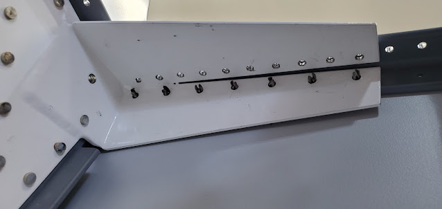
I clamped the new angle pieces in place under the channel and match drilled the vertical portion to the vertical arm of the seat back support.  The 4 holes that I originally miss-drilled go in the big blank part of the angle in the picture below.  In the picture you can see the three skin rivets that are the problem.  Two of them LOOK accessible in the picture, but in reality they are buried next to the angle and a bucking bar can't get anywhere near them.  You can barely see the third rivet hole - it goes into the white tab right at the vertex of the angle.  Not a chance.  So that's why I can't rivet in the angle until after I've put the top skin on later.


After hours remaking the angle pieces and drilling them in place, next up was the canopy deck plate (F-757-T)


The plate sits on top of the channel and nests underneath the longeron.  The four clecos in the top are the holes that started this whole rebuild - my original holes were about an 1/8" off on both sides.


With the 757 plates in place, I then measured, drilled and countersunk holes in the longeron that will tie it all together (eventually, after those three pesky rivets are done for the top skin).

I've been waffling on whether or not to bite the bullet and do the Antisplat mod that allows the seats to recline a few inches further.  The big benefit isn't so much the extra recline, but the fact that it gives more shoulder offset between passenger and pilot (one seat in the normal position, the other a few inches back).  The problem is that the mod was designed for the sliding canopy.  It can be done for the tipup, but because of the latching mechanism it takes quite a bit of extra work to make it happen.  I had Rose come out and sit in the plane with me (should have gotten a picture - it was the first time of many that we'll be in here together!).  We're both small enough that even with the standard setup we have a couple of inches between our shoulders.  Given that, I just decided to stick with the existing design.  Yes, it'll be tight on the occasions that I take someone for a ride who is wider at the shoulders, but I still think it'll be fine.  The bang for the buck isn't worth it considering the number of times I'd want the extra shoulder room anyway.