Sunday, November 19, 2023

Fuel Vents

Next up in the instructions is the section on fitting the wings temporarily to set the incidence and a number of other things. I'm going to wait on doing all of that, since it would mean reconfiguring the garage to give me enough space to put the wings on.  I'll come back to it later when I can more easily move benches and/or cars outside with better weather.

That means it's time to start with the fuel system.  After spending most of the day blowing out the sprinkler system, I didn't have much time left, so I just worked on the fuel vent fittings.  These are standard fittings that are modified to act as fuel vents.  I put each fitting in the drill press and took a file to the threads on the bottom half to smooth it out.  This wasn't all that necessary, but I think it'll look better than leaving the threads.  After it was smoothed out, I cut each fitting at a 45.  I'll have to find some screen to proseal over the opening to keep the bugs out.


Saturday, November 18, 2023

Gear Towers (4) & Seat Ideas

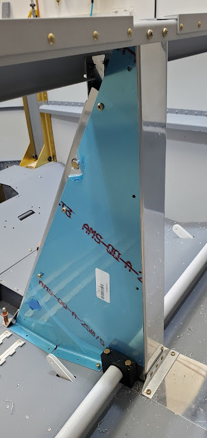
Today I spent about 2 hours putting in 10 bolts and 4 screws.  The gear towers have a flange that sits against the outside skin.  This is a blank flange that has to be match drilled to some pre-existing holes in the skins.  It's an easy task - the kind that always ends up taking longer than expected, between drilling the holes, cleaning them up, getting the bolts in, torqued, etc.

The arms that come forward have two holes that have to be drilled through the skin and then sized for a large screw.  The aft hole is easy to get at, but the forward one is buried behind the vertical support and there's no way to get to it from the inside to drill through to the skin.


I ended up drilling the aft hole that I could see to have a reference point on the outside skin.  The two holes are exactly 1" apart, thankfully.  So on the outside skin, I found where the blind hole SHOULD be, then using a very small drill bit I punched through the skin.  That was nerve wracking.  The small bit gave me some wiggle room to be a little off.  My measurements were close enough so the tiny hole mated up with the hole in the weldment arm.  Then I just started upsizing the drill bit size and letting it be guided by the steel hole.  Since steel is so much harder than the aluminum, by the time I had gone through a few bit sizes to the final 3/16", the holes were matched pretty well.  The arm is secured with two #10 screws and nuts.  I countersunk the skin and underlying aluminum layers enough to make the screw heads lie flat with the skin.


I don't necessarily have to order seats and an interior immediately, but given that there is a 6 month backlog at the company I'll be using, I may as well order sooner rather than later.  I'll be using Classic Aero.  They do absolutely beautiful work and have been making interiors for RVs for many years.  They sent me leather and carpet samples a while back.  Picking color combinations and styles has been easier said than done!  There are too many choices! I want a base color of grey for the interior since it will go with just about any exterior color I end up choosing.  I wasn't sure what combo of greys to use, but then found a 10 year old photo by the company where they were showing their most recent interior kit for the RV14.  The specifics are obviously different than the RV9, but I really like the two tone seats, the contrasting stitching, and the color of the carpet.  The one thing I haven't decided on yet is whether to go with their Aviator seats or their Sportsman seats.  The picture below is the Aviator.  The Sportsman is more basic (a little blockier and no contrasting stitching possible) and the Aviator has a little bit of a better foam, is more contoured, has integrated seat backs (so it wouldn't use the seat backs I slaved over to build), etc.  The Aviator is considerably more expensive of course!  I'll be putting seat heaters in them, regardless which style I choose.


The company sent me some basic ideas for layouts of the seats and the side panels.  The light grey portion in the lower front corner of the side panel is a carpeted cover for the gear towers.


Saturday, November 11, 2023

Gear Towers (3)

No exciting pictures, but I was able to get the right side gear tower mounted to the bulkhead.  The areas that caused problems on the left side were similar on the right, so it went a lot faster on the second side simply because I knew how to tackle it.  The bolts to the bulkhead are in place and torqued, but there are still a bunch of bolts remaining.  The flange of the weldment that lays against the side skin has to be drilled for bolts, and the arm that goes forward also needs to have holes drilled for two bolts through the skin.


Friday, November 10, 2023

Gear Towers (2)

The right side gear leg has been a bear to fit to the gear tower.  I wasn't able to get it to insert all of the way into the weldment, so I thought I'd just pull it out, figure out what was binding, then put it back in to ream the matching holes.  That simple act of  "just pulling it out" ended up being quite the ordeal.  I tried and tried, but I couldn't get it to budge no matter what I did.  Finally, with a couple of people helping, we got it out.  I had to clamp the weldment to the bench, have two people standing on the bench to keep it from moving, heat up the weldment, put a pipe in the axle for leverage to twist, then hit the upper end of the leg with my rivet gun while twisting the axle.  That popped it out.  It turns out the powder coating on the leg extended about 1/4" to far up the leg and was jamming into the weldment.  I filed off the excess powder coating, and with that the leg slipped right into place.  I reamed the holes in the weldment and leg and then stored the leg for later.


The gear weldment gets bolted to the bulkhead (the wing spar carry through) next.  No matter what I did, the weldment would not sit flat against the bulkhead.  The outboard section stuck up about 1/8".


The weldment itself has a bit of a bow to it, but part of the problem with it not fitting against the bulkhead was also that the weld on the back side stuck way out beyond flush.  I took a file to the weld to knock it down.


With that, the gear tower fit relatively well.  The bow in it still made it stick out from the bulkhead a bit, but it was close enough that it should be fine once the wing spar bolts go in.


The bolts that attach the weldment to the bulkhead are really difficult to get a wrench on, let alone a torque wrench.  For the upper bolts, I used a wrench on the end of my torque wrench (with the appropriate calculations to compensate for the additional length).  For the lower bolts, there was no way to get the torque wrench on the nut side, so I had to torque from the bolt head side.  That's not ideal, but there is no other way to do it.


Sunday, November 5, 2023

Gear Towers

Count today as a few hours of work with zero real progress.  Although, if taking steps backwards is progress, I suppose I made tons of it.  Today was a day for catching up on house chores, so I figured I'd just do a couple of small tasks on the plane.  The gear legs need to be fit into the gear towers and the upper bolt hole through the parts reamed to size.  The left side slid right into place and was finished in a matter of minutes.  The right side took a little more persuasion to get it 99% in place, but nothing I could do would get it the last 1/16".  So now the issue is of course getting it back out so I can clean it up a bit more and try again!  After an hour of trying to get it to pop loose, I gave up.  I tried heating the tower, using penetrating spray, pounding on it with a hammer.  So far nothing has even budged it.  I'll have to rig it up in the vice somehow and pull out a sledge.  The tower is such an awkward shape that I don't know how I'll hold it in place though.


Since I couldn't get the right side finished, I thought I'd bolt the left tower into place.  This is one of those times where I really want to yell at the engineer who drew up the drawings.  I made the floor stiffeners the exact size they said to.  What they failed to point out is that one of the arms of the gear tower has to fit between the stiffener and the bulkhead web.  Trimming 1/16" off the end of the stiffener is going to be a nightmare at this point.  It's too close to the bulkhead to fit any kind of a saw or cutoff disc, and even if I could, the last thing I want to do is nick this bulkhead (it's the wing spar carry through).  So somehow I have to figure out a way to take off some material from the stiffener.  I have no idea how I'll manage that.


Saturday, November 4, 2023

Flap Controls (2)

I installed the flap weldment (again).  I'm still not sure if I'll need to take it out again at some point, so I haven't put all of the bolts in yet though.


The flap mechanisms get covered up by a triangular box that sits above the center tunnel.  I started by putting the rectangular plate on the side of the front cover and match drilling it.  This is the plate that holds the bolt to mount the flap motor.  I installed platenuts around the sides of the cover, as well as prepped and match drilled the two angle pieces that attach the bottom of the cover with the seat floor (with screws - everything is removable).


I waffled on whether I should go ahead and rivet parts together or dump it all in the "to be primed" pile.  There are so many pieces, I don't want to have it all put together with clecos forever though.  I decided to rivet as much as I can together (with mating surfaces primed), as long as I can easily prime the full assemblies later.


The drawing for the flap controls and covers are the worst so far.  You can definitely tell that different pages were drawn by different people.  There are a lot of areas where the information on the drawings just isn't enough to be certain about how things go together, what hardware to use, rivet callouts, etc.  It can all be figured out, but it takes a lot of trial and error and head scratching.

I screwed the front cover to the floor and put the bent plate in place that connects the cover with the seatback bulkhead.  Without drawing measurements, this took a lot of shifting of things around until I finally got everything in a place where it lined up.  I match drilled the plate to the bulkhead and cover, then riveted on the nutplates for the bulkhead screws and riveted it to the cover itself.


The flap actuator needs to be at mid-stroke to get it mounted in the right position.  I borrowed the 4Runner battery and ran the actuator in and out to find the max travel, then marked the midpoint and stopped it at that point.


The end of the actuator that has the rod end bearing attached was bolted to the forward facing clevis on the flap weldment.  The upper end where the motor is nests into the front cover.  The spacer dimensions that the plans said to make was a little short and allowed the motor to sit at an angle.  I was going to make a new spacer to add about 1/16", but a thick washer ended up being about the right size, so I just went with that instead.  The whole point in doing this was to put the 766B angle piece that I had made yesterday in place.  I had already pre-drilled a bolt hole, but the 3 holes to attach the angle to the cover have to be drilled.  Once I was happy with where the motor was at, I clamped the angle in place and match drilled it to the cover.  Then I riveted it in place.


I riveted the 785B attach angle to the bottom of the backrest brace.  This brace acts as both a stiffener for the bulkhead as well as the rear cover of the flap motor.  Like everything else, it'll be attached with screws.


I put the sides on to match drill to the backrest brace.  The left cover runs right across the flap motor mount bolt, so I cut away some material to clear the bolt head.


Last up for the day were the nutplates on the backrest brace.  With that, the flap controls and covers are largely done.  The only piece remaining is the flap position sensor.  I'll take a look at that tomorrow.


Friday, November 3, 2023

Flap Controls

The flap "actuator weldment" sits behind the seat bulkhead assembly.  It has a forward facing arm that connects with the flap motor, and the rear facing arms connect with the flap pushrods themselves.  I forgot to take pictures of all of the little things that had to be done to get it to the point where it was ready to go into the plane (the picture below is still just a test fit).  The two plastic blocks on either end that bolt to the bulkhead were super tight, to the point that I was afraid the flap motor wouldn't have enough torque to move things.  I re-drilled the 1" hole through each block just to make sure it was the right size (it took off just a tiny bit more material) then took emery cloth to the weldment itself until everything fit a little better.  It's still stiff, but within reason and will probably loosen up pretty quick as the metal burnishes the plastic.  After having the weldment and those side blocks in and out about 50 times to get a good fit, I temporarily bolted the blocks in so I could place the center supporting block in position.  That block (black - hard to see in the picture) also has a 1" hole in it, then got split down the center.  Two bolts will connect the two halves and go into nutplates in the floor.  I had drill into the floors using the block as a template, then rivet nutplates to the floor.  Once all of that was done, I pulled the weldment out and put boiled linseed oil in it as corrosion protection.  I'm letting it drip dry for a day or two, then I'll re-install everything and torque the bolts down.


There are a lot of small pieces that go into mounting the flap motor.  Easy, but fiddly and took a while.  I haven't even figured out where all of the pieces go yet.  First up was a simple flap actuator plate.  The hardest part was locating the right piece of aluminum to use for it.


The flap actuator angle was next.


A piece of attach angle connects to the backrest brace (not in place yet) and ties it into the floor.  The bottom two holes were match drilled to the baggage area tunnel cover.  It'll get screwed in place with the tunnel cover so the cover is still removable.


Last up for today was another attach plate.  This one ties the front cover of the flap actuator to the top seat bulkhead.  For whatever reason, Van's didn't include any dimensions for this part, other than the laughable direction to bend an angle of 151.8 degrees into the part.  Right, I'll hit that exactly using my vice and pliers.  I have no idea why they don't even include dimensions of the part itself.  The drawing is to scale, so I guess they just figure you can measure the drawing, so why waste the ink?  With a few trips back and forth to the vice, I got a bend that was close enough.