Monday, March 31, 2025

EMS & Inventory

As I was pouring through documentation from different vendors and trying to wrap my head around how the whole FWF is going to go together, I realized I had never found a location for the EMS module (all of the engine sensors).  It has two big D-subs that come to it from the engine, then it connects to the "skyview network" on the ACM.  The skyview network is just Dynon's term for their network that ties all of the different modules together.  The ACM just consolidates that into one location.

I decided to mount the EMS on the left subpanel rib.  I've tried to keep as much as possible out of this area since it'll be covered up by a skin and the only access will be by crawling underneath the panel.  There's not much to this particular setup though.  If the module were to ever go bad, it'd be relatively easy to deal with even though I would have to lay under the panel.  I'll put a hole in the firewall in front of this unit (and a similar hole on the opposite side of the firewall for additional wiring), then I'll probably put a hole in the subpanel to take the wire from the EMS to the ACM.


My FWF parts finally arrived!  There's not much to show, but I spent the standard couple of hours hunched over the table doing inventory.  Everything was accounted for.  So now the real head scratching begins.  Van's sent some additional drawings, but that's really all of the guidance there is.  I think I'll start with laying out the stuff I am fairly confident about the location of, like the battery box, starter relay, master relay, etc.


Saturday, March 29, 2025

Wheels - Mains

Not much to show today.  My FWF parts were supposed to be delivered today, but I missed the UPS truck, so now I have to wait until Monday.  There are just a handful of things left to do on the gear and wheels before they are ready to be assembled.  Once I get the new primer this coming week, I'll spray the parts and do final assembly.

It's hard to show in a picture until the parts get bolted together, but the inside bracket that the main gear wheel fairing attaches to needs spacers to hold it away from the brake disc.  It's kind of pathetic how long it takes to make simple spacers, especially when they all need to be the exact same length.

The last thing the main wheels need is for the axle to be drilled to accept a cotter pin for the axle nut.  The nut is already drilled with holes in each face, but the axle does not have matching holes.  I put the inside and outside axle spacers on and tightened down the nut (just hand tight - it is only there to take side to side movement away and isn't supposed to get torqued down).  I spot drilled one hole then took the nut off and ground away the threads with a small round ball bit in the Dremel.  Hitting the threads with the Dremel made it much easier to center the drill vs trying to get it started on threads.  Once I had the first hole drilled, I put the nut back on and pinned it in place with a drill bit in the first hole.  Then I did the same process to get the opposing hole drilled.


Thursday, March 27, 2025

Brakes & Wheels

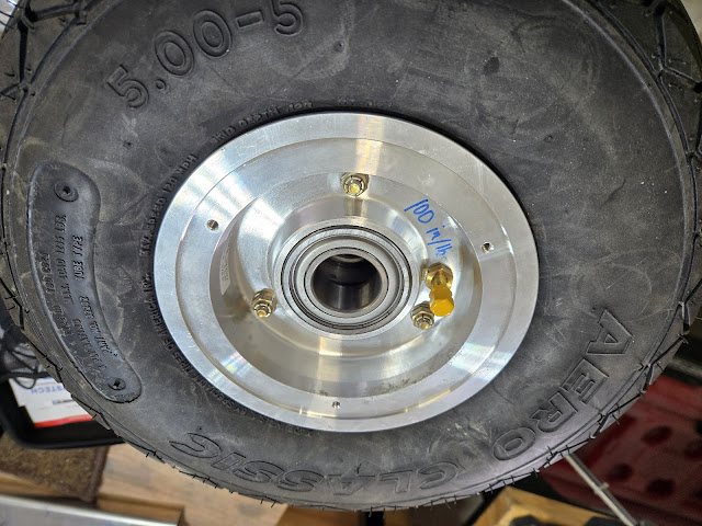
I already received my wheels back from having the bearing modification done.  This gave me a new set of things I could accomplish while I'm waiting on my firewall parts.  You can see the new sealed bearings they pressed into the wheel (one in each wheel half) in place of the tapered roller bearings that come with the wheels.  Having these new bearings will mean I don't have to repack bearings every year, and they should also help to keep the common issue of gear shimmy from happening (due to very finnicky axle nut torque, as well as worn bearings over time).  Even though the modification was initially developed for the nose wheel, it's now something the company offers for all wheels.  I went ahead and had them do the main gear wheels as well.

The wheels come split in half.  I used talc on the tubes and inside of the tires (allows the rubber to slide and minimize the chance of the tube getting wrinkled and caught in between the wheel halves or the tire bead).  The valve stem gets placed near a painted dot on the tire which indicates the lightest spot of the tire.  I inflated the tube just enough to have shape, then slide it into the tire, put the wheel halves in place, and torqued down the bolts.  On the main gear wheels, the bolts also hold on the brake discs.

The nose wheel is a little different than the mains.  It gets an axle insert (the blue piece) that slips between the fork, whereas for the main wheels the axle is part of the gear itself.


The other side of the nose wheel has a spacer and a nut.  All of this will slip in between the forks of the gear leg. 


The fork is a very solid chunk of material, but it was in pretty sorry shape.  I spent quite a bit of time trying to polish out all of the dings and cut marks, which I assume were just due to mishandling during manufacturing.  It'll all be hidden under a wheel pant, but I didn't want any possible stress risers in it that could potentially lead to cracking.  I want to give the fork a protective coat of primer since it'll be exposed to water, and I want to use an epoxy primer, which will be tougher than the typical primer I've used on the rest of the plane.  Even though I have a little bit of it left, I'm not really all that sold on the water borne epoxy primer I have used from Stewart Systems.  It's just not nearly as tough as an epoxy primer should be.  I ordered a quart of Kirker Enduroprime - it's an automotive 2 part epoxy primer that I've heard good things about.  Supposedly very tough, but not quite as expensive as the typical aviation epoxy primer.  So for now I'll move on from the nose wheel setup.


The main gear axle gets a brake flange bolted to it.  This provides an attach point for the brakes themselves.  The axle already has a 5/16 hole drilled through it, and the part with the flange has one hole that is the right size and one hole that is undersized.  Why they did that, I have no idea.  I needed to open up the smaller hole to 5/16, but I didn't want to do that with the part on the axle.  I probably could have put the flange on the axle and just used the hole in the axle as a guide, but I was afraid of the possibility of accidentally enlarging the axle hole.  I did it on the drill press instead.  That worked fine, although the hole (in both left and right gear pieces) was a hair off and made getting the bolt through a bit of a chore.


I still haven't quite wrapped my head around how the brakes attach.  The instructions are virtually non-existent, and the single drawing doesn't exactly scream clarity.


Piece by piece I'll figure it out though.  Each brake is mated to a piece of aluminum that is used as a mounting point for the wheel fairings.  These pieces still haven't been redesigned since Van's switched brands of brakes (20 years ago...), so they don't actually fit as-is.  I had to cut a half circle out of each plate so that it would fit around the upper bolt/pin on the brake mounting plate.


I'll probably keep working on the brakes tomorrow.  I'll get as much of it done as I can so that once I get the new primer I can just spray the parts and assemble right away.  I waffled on whether I should wait to do the brakes and wheels until the gear was installed on the fuselage.  I decided it's probably easier to put it all together first so that I only have to lift the plane once to install the gear vs lift it to install the gear, place the center fuselage back on blocks to keep the axles off the ground, then install the wheels and lift the plane again to get it off the blocks.

Sunday, March 23, 2025

Misc. While Waiting on FWF

My thumb twiddling continues.  I'm cautiously optimistic that Van's will get things shipped this week.  I have a lot of things left to do on the plane of course, but I don't really want to move everything around the shop only to have to move it back as soon as the firewall parts arrive.  So household chores it is!

I've decided I will do additional firewall insulation beyond what is in the kit.  The standard firewall is perfectly adequate, but there's a lot of evidence that shows insulating the firewall provides significantly more fire protection.  The bare firewall itself keeps actual fire from coming into the cockpit, but the heat transfer is pretty severe, meaning there's no way you'd be able to keep your feet near the pedals.  Adding just 1/8" of fiberfrax (covered with stainless steel foil), can keep the cockpit side of the firewall cool enough to make it a non-issue.

I made a poster board template of the firewall.  I'll use it to cut the fiberfrax and foil to size.  Once I figure out where everything goes on the firewall, I will temporarily mount it all, then remove it and transfer the hole locations to the template.  I think I'll probably have to buy some hole punches to punch holes in the foil and fiberfrax vs drilling.  The fiberfrax and foil will largely get held on with the stuff mounted on the firewall, but I'll use stainless sealed pop rivets in any areas that need it.  Anything that is structural on the firewall will be riveted/bolted/screwed on directly to the firewall and the insulation will be cut around it (like the engine mount pads).  Everything else that isn't structural, which is really just about everything, will get bolted on top of the insulation.  Fiberfrax is very dense and is fine to be sandwiched like this.  All perimeters will get a bead of 3M fire barrier caulk to not only seal it all up (mostly to minimize the chance of oil getting into the fiberfrax), but to also protect from the razor edges of stainless foil.  The foil I bought is actually stainless shim stock from McMaster - slightly cheaper than "foil" for some reason.  The widest it comes in is 24", so there will be seams where there is overlap.  The overlaps will be sealed with aluminum tape.  This seems counterintuitive, but the reason behind using aluminum tape and not stainless tape is that in the case of a fire, the aluminum tape will melt and open up the seam to allow the fiberfrax to off gas.


One small task I did check off today was dealing with the gaps present at the front of the canopy where the hinges insert.  The standard build just leaves about 1 1/2" of open space of the flange seal at the hinge blocks.  This is a common area of bad leaks and annoyance from what I've read.  This flange that is riveted to the sub panel will get a thin rubber bulb seal that the front edge of the canopy skin sets on top of.  Over that gap at the hinges it doesn't do much good though.  Most people don't seem to bother trying to fix the leak path.  Living in the PNW, there's no way I'm not at least attempting to improve it though.  The last thing I want is water pouring in on top of my very expensive instruments!

I decided to try to span the gap with material that the rubber seal can rest on, like the rest of the flange.  Doing the tiny step bend by hand was easier said than done, but after a few tries I got passable pieces.  I riveted them in place. There are still gaps, but those are small and will be filled with proseal when I'm ready to put the final top skin on.  It's not the prettiest solution, but I think it's as good as it can get for limiting leaks.  It'll mostly come down to how well that bulb seal works.  I didn't really need to make the pieces go forward over the hinge blocks like I did (the skin completely covers that area anyway), but it was simply easier to make.  I filed down the outside portion of the filler piece to make it thin enough that it'll go under the skin without causing any interference.


The other thing people often do is make or purchase a fabric cover for the subpanel area.  There is a company that sells them.  The idea is that even though most canopies will leak at those gaps, the fabric cover at least keeps the water from falling on instruments.  They attack velcro strips to the subpanel and the back of the panel, and the fabric just velcros in place just under the tip up frame.  I haven't decided if I'll go that route or not. I may wait to see how well my fix works.  I've been told the fabric is mostly useful when the canopy is opened on the ground after the plane has gotten soaked though - the canopy is big and that's a lot of water that runs off when it's opened.

Saturday, March 15, 2025

ACM Wiring (2)

I wasn't going to do much more on the wiring, but I also don't want to just twiddle my thumbs while I wait for Van's to ship me the firewall forward stuff.  I decided to clean up the subpanel wiring as much as I reasonably can at this point.  There are still a few wires to run that go in the "Aircraft Front" connector, but most of those come from areas that will route via future holes in the subpanel.  I bundled the left and right side wires and clamped them in place to send them behind the subpanel.  At some point when I'm extra sure there's no more wiring to add, I will make all of the bundles prettier and add a bunch more zip ties.  Most of the connections on the ACM that are still empty are for panel devices.

I have learned a few lessons for the next plane (which I'm sure I'll forget by the time I ever build again).  I should have given myself just a little bit more wire length and then put the service loops in before cutting the final lengths and crimping pins on.  I measured as best as I could when I did my initial wire runs throughout the airframe, and even though I gave myself a buffer, it was too close for comfort on some of the wires.  As is, I have some wires that were barely long enough to reach the ACM, and others that were long enough to give a decent service loop.  In the end it all works.  It just looks a little haphazard behind the scenes since there are varying size loops, no loops, etc.


Even though I don't have the Van's FWF parts, I did receive my exhaust from Vetterman in South Dakota.  He does really nice work.


Wednesday, March 12, 2025

ACM Wiring

Today was spent working on the connectors for the ACM.  Some of the connections won't be made until I buy the avionics (which come with wiring harnesses pre-built), but most of the wiring from the rest of the plane can be terminated at this point.  The Flyleds lights I bought came with a PCB that is an add-on to the ACM's Aircraft Rear connection, so that went on first.  Most of the pins just pass through unchanged, but for the lighting wiring, they do some fancy stuff with the board to allow for different light functions that wouldn't be possible otherwise. 


It looks like an absolute disaster, but there is a method to the madness.  Pretty much every D-Sub connector has wiring that is coming from both the right and left side, so the wire bundles have to split and go in different directions on the subpanel.  Right now the extra length of wire is just hanging down, but once I'm done it will be zip tied in bundles and route through a number of adel clamps.  For most of the wiring I left enough slack to leave a loop behind the subpanel, just in case I ever need to redo a connection and need a few extra inches.  I do have a couple of wires that don't have enough slack for a service loop, but that's not the end of the world - at least not a big enough deal to redo anything.

I had originally planned on labeling every single wire, but as I got rolling on making the connections, I realized that was kind of overkill.  Adding the clear shrink tubing over labels also really starts to make the bundles bulky and hard to manage.  For wiring that comes in as singles, I did label them.  But for wiring that comes in as a multi-conductor group, I just labeled the group (for example, instead of labeling all of the separate data wires in the elevator trim, I just labeled the whole shielded bundle "Elevator Trim").  I have a spreadsheet with all of my connections, including wire colors, so for future reference, as long as I can find the right bundle for "Roll Servo," I can then easily just reference the spreadsheet to know which wire I'm looking for.

AFS included a wiring harness for the ADSB and transponder (also includes the GPS connection) since those are panel devices and not coming from other parts of the plane.  The ADSB, GPS, and transponder all go into a single D-Sub on the ACM.  Unfortunately, they made the transponder bundle too short for my setup.  I chopped the old wire out and made a new harness about 8" longer.  Their harnesses are nice and professional looking with snakeskin wrap, so I gave that a shot just for kicks.  I was originally going to put snakeskin on all of my bundles just to make everything really clean looking, but with all of the offshoots it's not super practical.  Once I'm all done maybe I'll do some wire wrap on the big bundles.

I measured and made the coax terminations for the ADSB and transponder too.  I left extra length in the ADSB for a service loop, but I ran the transponder coax without much extra.  I'm already right at the edge for length on that antenna wire (signal starts to degrade if the coax gets too long for the transponder).  It's yet to be seen if all of my terminations are good!

I only have a few connections left.  The Dynon GPS connects to the pigtail harness that goes into the AFS made ADSB/Xpndr/GPS D-Sub.  I think they have that pigtail on the harness just so people don't have to add the GPS wires to the larger D-Sub at the ACM end.  I contemplated just pulling that pigtail out when I was fixing the transponder harness (then I'd just wire the GPS directly to that D-Sub vs using the pigtail), but decided not to bother.  Outside of that, I think the only other connection I have to make is for the ADAHRS.  I have that cut and pins crimped on, but I don't have the right D-Sub for it.  For some reason AFS made those D-Subs on the ACM male, whereas almost all of the rest are female.  That would be fine, except they only sent male 9 pin D-Subs, so I don't have a female mate to use for that ADAHRS.  I'm definitely getting my free shipping money's worth from Amazon these days.

Once I'm done with those connections, I think I'll be finished with wiring for now.  I would love to finalize these bundles and tidy them up, but I can't until I've gotten further on the firewall.  The vertical wire run up the firewall goes right over the top of a line of rivets on each side that won't be completed until I hang the engine, run control cables, and close out the big cutout in the firewall.  If I adel clamp the vertical wire runs in place now, I'll have to move them out of the way once I'm ready to rivet those stiffeners.

There are some wires that don't have a home in the ACM, like the heated seats power.  I'm not going to be using traditional circuit breakers for anything, but instead am just using a simple fuse block.  There's no reason I'd need to be able to reset heated seats in flight, so a fuse is fine for me.  In fact, many of the newer RV designs (like the RV12) use fuses almost exclusively.  Safe, light and low maintenance.  I haven't figured out yet where the fuse block is going to live though.  I may have to wait until I have the comm unit mounted to the subpanel and the center stack in place to know how much subpanel real estate I have left.  


Monday, March 10, 2025

Wiring Cleanup

My order for my firewall forward parts is still not here.  It's still just listed on Van's site as "preparing for shipment," which it's been for 3 weeks now.  I guess it's safe to say they still haven't gotten their operations under control.

I wasn't going to do any more work on wiring until after the firewall work was largely complete, but I'm tired of twiddling my thumbs.  I'm going to go ahead and figure out the wire routing and terminations for all of the wiring that I ran up to the front of the plane before.  I won't be able to finish it completely until I actually have the panel instruments to work around, but hopefully I can get some of the main runs done to the ACM.

The biggest hurdle so far is the 90 degree turn from the floor and up the firewall.  The wire bundles are so large that they don't make the turn, as well as then curl over the vertical stiffener to make the run upwards, all while staying compact enough at the floor to let the center tunnel cover lay flat.  That cover is the kicker.  It was designed 25 years ago when there was probably half the wiring that there is today.  The space allotted for the wiring and brake/fuel lines is just very tight.  I tried using conduit vs the wire wrap (the wire wrap makes the bundles really stiff), but it still doesn't work very well.  I may have to split the bundles in two to make the diameters smaller until they are running up the firewall stiffener.  The left side wires used to run over the top of the brake lines, but I couldn't get that to work, so I pulled it all out and reran the wire behind the brake lines.  I think that will work better, but I am still having issues getting the wiring to comply and go where it needs to.  This whole area feels like a design afterthought. I spent a few hours messing around with it, but had to give up for the day and do something else.  

Once the wire bundles reach the top of the firewall, I'll route them back to the subpanel.  I added a few adel clamps to the firewall stiffener, wire support bar and the bottom of the subpanel.  A lot of people drill holes in the subpanels for the wire to pass through, but not having the panel instruments yet, I didn't want to do that.  The GPS will require a big cutout in the subpanel, and there are still a few items to mount to the subpanel.  It's going to be tight, and I don't want to make wiring holes that then end up being in the way.  To get around that, I decided to run most of the wire along the bottom of the subpanel.  There will be a few wires that I do run through holes in the subpanel, but I'll wait to do those until all the instruments are in place.

Both the left and right wire bundles follow the same general path to the subpanel.  Since the ACM is on the left though, a bunch of wires from the right bundle will have to split off and travel along the bottom of the subpanel to the right side and join wires in the other bundle.  I put some adel clamps in place for that as well.  The way the ACM works, I will be combining wires from the left and right into single bundles to go into a specific D-Sub connector at the ACM.  So now the game is figuring out what the "right" length of the wires is, terminating them, labeling, etc.


Saturday, March 1, 2025

Nose Gear

I'm waiting on my firewall forward parts to arrive, and there aren't too many big tasks to do in the meantime.  I can't finish the engine mount until my 3/8" reamer arrives, but it looks like I can put the nose gear assembly together.  A number of years ago Van's changed the nose gear design from a simple gear leg that slid into a socket on the engine mount to a hinged setup with elastomers for shock absorption.  I assembled the shock (and then disassembled it when I realized I couldn't get the bolts in with the spring installed) and bolted it to the engine mount.


Once the nose gear is installed I will tighten the top nut to bottom out the spring.  Over time the elastomers will compress, so Van's provides a couple of 1/8" pads to install underneath the top plate when that happens.