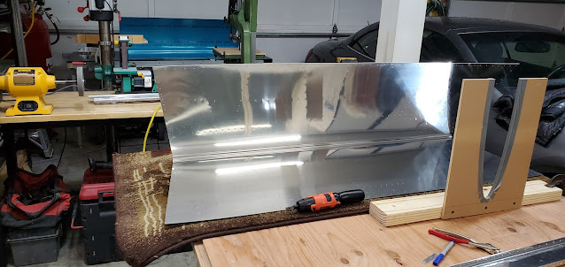
We started today by finishing the rudder. The mantra of "cleco, drill, disassemble, debur, dimple" is becoming very familiar already.
Thursday, September 30, 2021
Rudder & Primer Prep
Wednesday, September 29, 2021
Rudder
After the stiffeners were finally done, we started the rudder skeleton. This was pretty straight forward, aside from figuring out how the rudder horn is supposed to layer together with the lower rib. The plans just don't show the layout in enough detail to determine if the rudder horn goes on top of or underneath the rib flange.
Tuesday, September 28, 2021
Rudder
Today started by finishing up the vertical stabilizer from yesterday. It was disassembled and we deburred, countersunk and dimpled all holes and edges.
The rudder was next up on the list. The construction of the rudder is significantly different than the other surfaces we've worked on so far. It's shockingly light weight! Instead of having ribs for all of the support, there is only an upper and lower rib, and all of the support is actually provided by angles that act as stiffeners. Van's supplies a bundle of angle for the stiffeners. These all have to be cut and shaped to fit the rudder skin. The manual is woefully inadequate in describing how the full length angle needs to be cut to provide the correct number to match the skins. The pre-punched holes in the skin aren't evenly spaced, which makes it even more of a head scratcher. After a lot of trial and error, we finally figured out how to place and cut the stiffeners so that they all work out. Each stiffener gets cut (have to do so from the correct side to make it work out right!) according to marks Van's puts in the angle. We marked, cut, sanded, and deburred the stiffeners and clecoed to the skins.
Monday, September 27, 2021
Left Horizontal Stabilizer & Vertical Stabilizer
The right horizontal stabilizer was fitted yesterday, so today we disassembled everything and began deburring all holes and edges, as well as dimpling and countersinking. Deburring has been a little bit of an experiment. Thicker material seems okay to deburr with the Cleaveland deburring bit in the powered screwdriver, but in thin material the bit either creates too much of a countersink or doesn't actually remove the burr enough to matter. For thin material we found that using a reamer to match drill created such a smooth surface that deburring was not usually necessary. When it was necessary, instead of using a bit, running worn out sand paper over the surface was enough to flatten the burr. I researched deburring until blue in the face, and from what I've found, most commercial specs call for simply running something over the surface to remove the outer burr, but not worrying about creating any kind of a chamfer. In the future, I will be a little more free with just surface deburring vs using the bit.
The nose ribs of the horizontal stabilizer have a front flange tab that has a single hole in them. The edge distance is not what it should be, but I emailed Van's and they said this is very common for these ribs, and not to worry and build on.
After finishing the right stabilizer, we moved on to the left and repeated the exact same process. Following that, we started on the vertical stabilizer. This was actually considerably less involved and may have actually been a better place to start than the horizontal stabs. We clecoed and drilled the vertical spar and doublers, then the hinge brackets. After finishing the edges and fluting the ribs, those were match drilled to the spar as well. Attaching the skin to the vertical stabilizer skeleton was far easier than the horizontal stabs. It did not require a jig and wasn't nearly as tight of a fit.
Sunday, September 26, 2021
Right Horizontal Stabilizer
Dad and I deburred the edges and lightening holes of all the ribs prior to starting the assembly of the tail structure. For the most part, everything lines up with amazing accuracy. It something isn't fitting, it's likely that you've made a mistake! The main ribs and nose ribs are clecoed and match drilled.
Friday, September 24, 2021
Front Spar
The first parts are under construction! I started by clecoing the two front spars together using the doubler plate, then match drilled it all. Even though the RV9A is a relatively small plane, the length of the spar for the tail was a bit surprising.
Attached the attach brackets to the front spar and match drilled.
The last step for today was to cleco and match drill the hinge brackets to the rear spar.
Thursday, September 23, 2021
Here We Go!
After 5 months of waiting, my tail kit has arrived! It took about 2 hours to do a complete inventory, the only discrepancy being that I have one extra screw. Van’s does an amazing job of packing.


