Sunday, August 28, 2022

Aileron Pushrods

The small aileron to bellcrank pushrods are steel vs aluminum like the larger ones.  I measured where the rivets needed to go and drilled holes using the drill press. Most of the drilling went just fine, but for some reason one portion of the threaded pushrod end was incredibly hard compared to everywhere else.  I broke one drill bit and had to sharpen the second one 4 or 5 times before I finally got through.

The rivets used to pin these ends on are super long (4-12) and notorious for being difficult to set.  I didn't even bother trying to do it with the gun and bucking bar and went straight to the C frame.  That ended up working pretty well, except for the fact that I was short a couple of rivets and will have to order more to finish. 


The rivets aren't all pretty, but the forces are completely in shear, so ugly or even over-driven shop heads doesn't really matter too much.  The rivet just needs to stay in the hole.


Friday, August 26, 2022

Right Wing & Aileron Controls

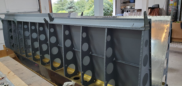
I don't have pictures of most of the steps, but with Dad here, we hammered through the right wing and got the top skins, J stringers, aileron and flap brackets, and gap fairings riveted on. It feels great to finally have this wing caught up with the other one!  The fuel tank took a little bit of work to get it mounted to where it laid nicely against the other leading edge and spar, but after tweaking a few things (including squeezing some of the rear baffle rivets a little more so they wouldn't hit the spar), we got it mated nicely.  Something for me to keep in mind in the future is that it's easier to "set" the tanks in the right position by using the screws through the skin vs starting with the z bracket bolts.

We moved the right wing off of the stand and set it in the cradle alongside the left wing.


We tackled the aileron control rods next.  The large aluminum tubes that connect the sticks to the aileron bellcranks were cut to the required length, then we primed the inside by flooding it with rattle can primer.  We pulled a partially inflated balloon through the tube to help spread the gobs and gobs of primer down the length of the tube.  Each end of the control rods got drilled for 6 blind rivets and the threaded rod ends were riveted on.  Ultimately, the rod end bearings will thread into these and be attached to the fuselage controls and aileron brackets.

The aileron bellcrank to aileron pushrod was up next.  This is powder coated steel vs the aluminum of the larger pushrods.  The plans could make life a little easier by simply indicating the length the pipe needs to be cut to.  Not sure why they don't, but after checking and double checking we finally figured out the length and used a hacksaw for the cut.  These tubes are much smaller, so we simply poured some primer in them and sloshed it around until the insides were coated.  Next up will be drilling these and riveting on the rod ends.


We installed the aileron bellcranks onto the right and left wing spars next.  Not all of the bolts can be put in place permanently until the pushrods are primed and installed, but we put in the bolts we could and torqued them to spec.  All final torqued bolts got torque seal applied so I have an indicator of which ones have been completed.


Sunday, August 21, 2022

Flaps (3)

I've been delinquent in posting progress from this past week, mostly because there aren't a lot of pictures to share.  The last step in pre-building the flaps was to drill the trailing edge and drill the inboard plate that mates to the rib and the angle I fabricated earlier (still just working on the left flap - Van's is sending a new main rib for the right flap since the kit was missing one).  The large hole in the tip of the plate will get a nut plate and eventually a bolt.


That was A LOT of trailing edge holes to drill!  The wedge gets located by using the other flap wedge to butt up against the ribs.


With all of that done, I started to take everything apart for deburring and primer prep.  One thing I did decide to do was order new nose ribs though, so I'll have to deal with re-drilling them once they arrive.  The problem was I did what the manual calls out to do for all other nose ribs, only realizing after the fact that it caused a problem. For all other nose ribs you need to run the front couple of flange tabs against the scotch brite wheel to round them a bit more.  Otherwise the bend in the flange hits the skin and puts a dent in it.  I went ahead and did that step because in looking at the flange bend, it definitely would have hit the skin.  The problem is that these ribs are made of much thinner material than all of the other ribs up to this point.  So when I rounded the edges, it took off enough material to make probably 50% of the real estate on each tab extremely thin. It was so thin that taking a file to it to try to correct it just flaked off chunks of aluminum.  Van's said I could probably use them as-is since those front flanges don't really take any abuse, but the material is so thin that I'm pretty sure it would crack at some point, and replacing them down the road would be next to impossible without rebuilding the flap.  So I'm just going to replace them.

This is a good nose rib. I don't have a picture of the bad ones, but those leading edge flange tabs are about half the size on the goofed up versions.


Sunday, August 14, 2022

Flaps (2)

I forgot to take pictures of it, but the first step today was making a bracket out of aluminum angle.  This bracket is what an end plate rivets to on the inboard rib.  The only difficult thing about making it was the fact that none of the dimensions are 90 degree angles, and interpreting the plans took a little head cocking, especially when I had to translate the left angle illustrated into what the angles would look like for the right side.  The bracket also gets a small shim underneath part of it, since the inner portion of the bracket sits up on the nose rib flange.  Once made, I clamped everything to the spar and drilled all of the necessary holes.


Next up was to cleco the bottom skin to the spar and drill every other hole in the skin into the workbench for clecos.


In a few steps, the skin needs to be able to be clecoed from the outside, but still lay flat on the bench.  To accomplish this, the holes I had just made to cleco the bottom skin to the bench had to be enlarged so the whole body of the cleco could fit down through the table.  This takes a 5/8" bit, which I didn't have on hand.  The largest bit I could find (outside of a 1" forstner, which just seemed excessive) was a 1/2", so I just used that and wallowed out the holes a little bit to fit the clecos.  I did both the left and right flaps up through this point.

I clecoed the ribs to the spar, then flipped the flap upside down and clecoed the bottom skin to the ribs.  This is where I got stuck on the right flap.  It turns out Van's mislabeled a rib, so instead of getting 9 rights and 9 lefts, I got 8 rights and 10 lefts.  So unfortunately I can't continue on with the right flap until they send the right part. 


After that, I flipped the flap again to let the bottom skin lay flat on the bench with the clecos sticking through the holes.  Next up, attaching the nose skins to the spar.


While the nose skins weren't quite as tight as they were on the ailerons, they still took a lot of manhandling to get fit.  I ended up taking things apart more than once to work on the flanges on the nose ribs - they don't have a smooth curve to them, which may make the skin fit harder than it needs to be.  I used the scotch brite wheel to knock off some of the edges on the very front flanges, basically like I did on the leading edges of the wings.  This helped a little bit, but not enough that I could get the skins clecoed to the spar by hand.  I finally pulled out a ratchet strap and went that route again.

I ended the day by final drilling all of the skin to spar and nose rib holes.


Saturday, August 13, 2022

Flaps

I didn't get to spend much time in the garage today.  I just took a few minutes to drill the flap hinge brackets to the spars.


Friday, August 12, 2022

Aileron Brackets & Flaps

The aileron hinge brackets are powder coated.  Since they'll get painted along with the rest of the plane, I considered not attaching them to the ailerons yet.  I asked on VAF and people said to go ahead and put them on since ideally all aileron rigging should be done prior to paint (even though you then have to take the ailerons off to paint them).  The powder coat has to be scuffed for paint to stick, so I went ahead and scuffed it with scotch brite before bolting everything together.

There are only a few bolts to deal with, but it took quite a while since none of my wrenches fit into the spaces very easily.  I ended up grinding off one side of an old 3/8" socket so it would fit on the bolt heads without hitting the side of the bracket.  These bolts only get torqued to 20-25 inch-lbs, but since the nuts have a nylon insert to lock them, first you have to run them on part way, figure out what the friction torque is for them, then add that to the torque spec for the bolt.  For example, using a beam style torque wrench to test them, I saw that these nuts take about 8 inch lbs to turn, so adding the 8 to the spec gives 28-33 inch lbs for the bolt to be properly torqued.  If you don't take into account the torque require to turn the nut on the bolt before it even hits the material, setting the torque wrench to 20 would mean you really only have 12 inch lbs on the bolt.  I did the same test for the inside bolt that goes into the plate nut.  The plate nut had a much higher friction on it - something around 15 inch lbs if I remember right.  After everything was torqued I put torque seal on each nut (or bolt, in the case of the plate nut that is inside the aileron and not accessible) as a visual indicator that those were torqued.


So  both ailerons are now done and ready for rigging.  I'll just store them until the right wing is done, then I'll finish up with all of the control rods and push tubes and get them temporarily mounted and out of the way.

Next up, flaps!  It looks like this is going to be very similar to the ailerons, only at twice the scale.  One major difference is the flaps use ribs instead of just stiffeners like the ailerons do though.  I pulled out all of the parts and clecoed and match drilled the hinge bracket assemblies.  There are three of these per flap.  I'm going to work on both flaps at the same time, assuming I have enough room on my bench without making it too awkward to work.  If I don't, I'll at least have all of the parts ready to go and can then assemble one flap at a time.


Wednesday, August 10, 2022

Right Aileron (3)

I finished up the right aileron this afternoon.  The trailing edge of the left aileron turned out fine, but having learned a few things, the right aileron turned out very good in comparison.  The last item for the ailerons is to attach the brackets on each end that then get bolted to the brackets on the wing.  I am waiting on Amazon to deliver a single 3/16" bit so I can drill the bolt holes and finish though.  I have normal length 3/16" bits, but they are too short and the chuck of the drill can't clear the end ribs.


Monday, August 8, 2022

Right Aileron (2)

I finished up the right aileron spar/skin riveting today.  I still have the main ribs to skin riveting to do, as well as the trailing edge, but I'm going to wait until after I finish the trailing edge on the left aileron to see how that goes.


Sunday, August 7, 2022

Left Aileron (3) & Right Aileron

Sleep does wonders.  I ended the build yesterday scratching my head over how I could deal with the clecos that kept popping out of the aileron spar.  The space is just too small to get my hand in there while holding the little aluminum keepers that would give the clecos something to grab onto.  The problem wasn't getting a flat hand in, it was that a flat hand triples in width when you have to use your thumb to hold onto something with a finger.

This morning I had a "well duh" moment.  The simple solution was to just wrap some electrical tape around my finger, then stick the aluminum keeper under the tape.  That was enough to keep the keeper in place and let my flat hand slide in between the skins and back to the spar.  With that figured out, it didn't take long to fix all of the sloppy clecos and move on to the next thing.


Now that the clecos were actually holding things together solidly, I could move on to actual riveting.  I repurposed my old fuel tank jigs to have something to stand the aileron up in.  I just traced out the nose rib and cut two pieces of junk plywood, then screwed them to the old jigs.  It's ugly, and I could have built them from scratch, but they're just throwaway tools, so good enough is good enough for me.  They worked great.


I didn't get a picture of the first few rivets to go in.  First were the nose skin to nose rib rivets on both sides, then the pop rivets that hold the nose skin to the counter balance tube.  After that, the fun started - ripping off most of the skin on my arm squeezing it in between the skins to rivet the skins to the spar.


It's hard to visualize, but it's tight in there (I wore a glove to keep my hand from getting too chewed up)!  I used my small tungsten bucking bar for most rivets - basically just setting it on the spar and trying to keep pressure on it with two fingers.  The rivets that are around the stiffeners couldn't be done with the square bucking bar because the stiffeners are in the way.  Thankfully I have a chunk of metal that is kind of in a S shape which worked really well here (in the picture below, the main body is wrapped in blue tape, then one of the feet that sticks down and out and slides under the stiffeners is wrapped in the red tape).  Again, it wasn't easy to put pressure on it, but since the rivets are tiny 3-3.5s, they set pretty easy even without a lot of pressure.  The plans call out 3-3 rivets for all of the skin to spar holes, but those were too short in my opinion.  The 3.5s are maybe a tiny bit longer than necessary, but they weren't so long that I had trouble with them folding over.  They worked much better than the 3-3s.  I 


The initial learning curve was slow, but once I was half way done with the top side, I had it pretty well figured out and could move along at a decent clip.  I finished the top skin, then turned the jig around and finished the bottom.  The one thing I did learn was that if the mushroom set of the rivet gun slides up from the edge of the spar/nose skin and onto the main skin, a nice ding will appear.  So I have two small dings that will get some filler once it's time for paint!

After the skin to spar rivets were finished, I pulled the aileron out of the jig and squeezed the main rib to skin rivets on both ends.


The last step (at least for the aileron body itself) is the trailing edge.  Time will tell if I learned anything from my experiences doing trailing edges on the tail.  There are three options for trying to keep the trailing edge straight for riveting: 1) proseal the wedge in and cleco it in place, then rivet when the proseal is cured, 2) use 3M VHB tape to do the same job as the proseal, but without the mess, or 3) do nothing and just go straight to riveting.  Most people do the proseal simply because that's the old school method that Van's used to use. Now Van's recommends the tape, just because it's not nearly the mess.  There is nothing structural about any of it.  Whether proseal or tape, the purpose is simply to try to stick the parts together enough that they make back riveting the trailing edge a little easier, and make straightness a little more attainable.

I'm going with the tape.  It sure doesn't seem like much of anything, but once it grabs hold of something, it's a pretty solid bond.  It's super, super thin - kind of looks like cellophane once the backing is pulled off.  It still blows my mind that it does anything.  I cleaned the wedge with acetone, then laid the tape onto it on both sides.  Once adhered to the wedge, I pulled the backing off and slid it in between the skins.  Then I pulled the backing off the second side and clecoed everything back down onto the table top using the holes I created when I originally match drilled the wedge to the skins.


The 3M tape is supposed to hit it's 100% adhesion strength after about 72 hours at room temperature.  It's warmer than that, so it'll probably end up being a little quicker.  I have the right aileron to work on, so I'll just wait a few days before I go back to riveting the trailing edge.


The right aileron went together in a fraction of the time, mostly because I had just figured out all of the gotchas while working on the left one.  The manual is great, but sometimes the order they have you do things in kind of causes headaches down the road. For example, they have you cleco the main ribs to the skins and then cleco the skins to the spar and rivet.  There's no way I could get my hand in between the skins to work with the ribs attached.  I had to remove the clecos from the ribs so I could bend the skins enough to get my hand in place.  That obviously didn't take long to undo, but there are quite a few gotchas like that, and the build/rebuild time as you figure out the issues can add up.  So anyway, the right aileron went together extremely quickly since I knew exactly how I wanted to approach it.


The biggest time saver was knowing how I'd deal with the clecos holding the nose skin to the spar.  It probably took me 10% of the time it took to do the left aileron.

So there it sits now, ready for riveting on another day.


Saturday, August 6, 2022

Left Aileron (2)

I got a lot done today, and also not a lot, depending on the perspective.  I should have gotten quite a bit more done, but ran into some difficulties.

First I scuffed and cleaned all of the remaining parts for both the right and left ailerons and got them primed.


I started on the left aileron.  The first few steps are simple - just rivet on the doublers to the spar.


Then the nose ribs got pop riveted to the counter balance tube.

Followed by the nose rib being riveted to the spar.


Lastly the main end ribs got riveted onto the spar.  The center two rivets are countersunk to account for an attach bracket that is put on later.  The outside holes will be drilled to final size once the brackets are on (these holes get bolts).

This is when I ran into trouble.  I clecoed the lower skin to the ribs, followed by the top skin to the ribs.  Then the instructions are a repeated of how the aileron went together earlier.  I clecoed the lower skin to the spar, then the bottom nose skin, then did my ratchet strap dance and got the top skin and nose skin clecoed to the spar.  I thought "easy!" as I finished up.  As soon as I released the straps, the aileron sprung to life and virtually all of the clecos in the top and bottom skin popped out.  The aileron looked like a twisted mess sitting there, and I was afraid it had been damaged, but thankfully everything was fine.  The issue is that the spar is countersunk, not dimpled, because the thickness is right on the edge of being too thick to dimple (dimpling would cause it to warp).  The problem is that means it's also on the edge of being too thin to countersink.  In order to get an appropriately deep countersink to accommodate the dimpled skin, the countersink just barely busts through the other side of the material.  That makes the center hole a little bit bigger than it would be if the material were thicker.  This is fine in this situation (apparently, since that's what Van's specifies), but the slightly larger hole means the clecos won't hold.  The only solution is to put something for the cleco to grab behind the enlarged hole.  I took everything apart and started over again.  For the bottom skin, it was relatively easy since I had access to the spar.  I have a bunch of little pieces of aluminum that are drilled to #40 that I keep around just for this.


The problem is the top skin.  Once it is ratcheted onto the spar, there is very little room to get my hand in between the skins to blindly put these keepers in place.  I'll have to get my hand in for riveting, but that doesn't require me to have an itty bitty piece of aluminum squeezed between two fingers.  I finally gave up after getting just two or three on.  I'll try again tomorrow when my patience is fresh.  I'm thinking it might be easier if I got some small nuts vs using the aluminum.  Nuts may just be easier to balance on a finger tip.


Thursday, August 4, 2022

Left Aileron

It took a lot of  muttering under my breath, but I finally got the nose skin wrapped around the counter weight tube and clecoed to the top skin and spar.  It was insanely tight!  It made the tank skins seem like a walk in the park.  In the end, I had to use ratchet straps that went over and under the bench to pull the skin to the spar (very carefully).

As the nose skin gets clecoed to the spar, the top aileron skin turns into a wave from the tension.  This is apparently normal, but it sure is disconcerting to see.


Now the reason for the ultra flat bench top comes into play.  Because of the tension and top skin wave, the entire structure has to be weighted down so it lies flat on the table during match drilling to the spar and when the trailing edge is drilled.  First I match drilled the nose skin to the spar, and also match drilled the counter weight tube to the holes in the skin.  Drilling the tube was easier than I thought - slow speed with Boelube worked pretty well.


Next up was the trailing edge.  This uses a wedge, just like the elevators did.  To keep everything as flat as possible, I drilled into the bench top and clecoed every hole as I went.


That's everything for the aileron.  Well, except the fact that I have to take it all apart, deburr, dimple, countersink, prime, etc.  Most of the parts get dimpled, but the spar gets countersunk due to its thickness.

The last step in prepping the parts was countersinking the wedge.  The last time I did this, I took a while to set the drill press up at an angle and used a jig to hold the wedge in place.  It worked fine, but was kind of fiddly.  This time I took a different approach.  Tool makers sell a tool specifically for countersinking the wedges.  It's simply a piece of metal bar that has an angle cut out that mirrors the wedge, essentially allowing the top surface of the wedge to be flat and perpendicular to the drill.  I unashamedly stole the idea and just printed it on the 3D printer instead.


This worked great.  Because the material is countersunk on both sides, the hole gets enlarged as the countersinks meet up.  Without a solid setup, the countersink bit wallows and creates a nasty looking hole that is way too big.  The drill press setup ensures that the bit doesn't wander.  The black electrical tape is just there to keep the cage from spinning with the bit as it's lowered.


So all parts of the left aileron are ready for priming.  I think I will go ahead and repeat everything for the right aileron before assembling the left one.  That way I can prime all parts in one batch vs having to pull the spray gun out multiple times.


Wednesday, August 3, 2022

Ailerons (Mostly Left)

I didn't take any pictures or do a write-up, but yesterday I prepped and primed the aileron skins and stiffeners.


Today I started out by back riveting the stiffeners to the skins.  I sure wish all riveting was this easy!  Back riveting goes really quickly and always turns out really nice.


The next step was to cleco the end ribs to the spar and match drill to the bottom skins.  The ribs are not symmetrical, so I had to be careful to ensure I got them in the right place so the skin holes would line up.


After the skins and ribs were match drilled, the skin holes got dimpled with the squeezer.  I dimpled as many holes in the ribs as I could with the squeezer, but the last couple were too tight to get the squeezer yoke into.  The close quarters dimple die worked great though - just a female die bolted to the bench and the male die inserted into the ram from the C-frame dimpler.  A couple of hits with a heavy hammer made nice dimples.


In order to match drill the top skin to the rib, the bottom skin has to be able to lie flat on the table.  The only way to do that is to temporarily rivet the rib to the bottom skin, since clecos would get in the way.  So I put two rivets in each rib, just barely set to make them easier to drill out later.


Now is time for the part I need to figure out how to do - wrapping the leading edge into shape and clecoing it to the top skin/spar.  I clecoed the bottom side of the leading edge skin to the bottom skin and spar, then slid the clecos off the table and clamped everything down flat.


Of course, the instructions failed to call out that the nose rib and counterweight tube should be in place, so I had to back up and get it clecoed in.  With the tube in place, bending the leading edge around and connecting it to the top of the spar is going to be a fight and a half.  It is tight!  By hand, I can only get the holes to be within about 1/4" of each other.  So I'm going to have to figure out another method for this.  Time to do some research and figure out what others have done!