Sunday, December 31, 2023

Strobes/Position Lights

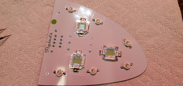
The Flyled wingtip lighting takes a lot more work to put together than the landing lights.  The circuit boards are the right general shape for the wing tips, but are far from a match.  This isn't the fault of Flyleds - the Van's fiberglass parts are known for being a bit rough. I shaped all of the boards on the sander until they fit.


Step 1 was to bend the tabs on all of the white strobe lights to give a foot to solder to the control boards.


I spread a very thin layer of thermal grease on the back of each LED and then put them in place on the boards.  The thermal grease just helps transfer heat from the LED to the control board.


After soldering the strobe LEDs, the position lights were next.  These things are tiny! Like the strobes, they get thermal grease on the back. The + and - markings on these were incredibly hard to see.  I had soldered one and a half boards before I happened to notice something - the right side should get green position lights.  I had just grabbed the position lights from the little bag marked "G" and not given it a second thought.  It wasn't until I was partially through the second board when I noticed the LEDs had a very, very tiny red dot in them.  It turns out the bags were switched.  The green lights are basically clear in the middle (no green).  I guess that's the joy of solder - easy to undo.  I unsoldered everything and grabbed the green lights from the bag marked "red."  I will say my soldering skills won't win any prizes, but it's serviceable. It all looks a bit dirty from the flux, but I'll clean it up after I'm all done.


With all of the lights soldered in place, next up were the resistors and wiring mounts.  The green position lights get a different resistor size than the red.  The popsicle sticks are simply there to help offset the resistors so they don't lay on the board.  Apparently they build up a considerable amount of heat, so keeping them about 1/16" off the board helps dissipate the heat.


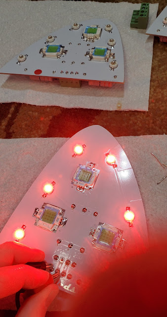
After chopping off all of the resister and wire mount wires, it's time to test!  Even though this is built for a 12v system, the instructions recommend just testing with a 9v battery to keep from burning your eyeballs.  It's shocking how bright these things are!  The one issue I ran into was that on one of the left side boards, one row of position lights wasn't working.  They are wired in series, so after looking at them a bit closer I saw that I had gotten the polarity of one of the lights backwards, which would keep the entire line from working.  After fixing that, everything worked perfectly.  The hardest part of the day was taking a picture with one hand while testing with the other.


The white strobes still have the blue protective plastic on them.  I'll probably just leave that in place until I install everything in the plane.


Saturday, December 30, 2023

Brakes & Landing Lights (2)

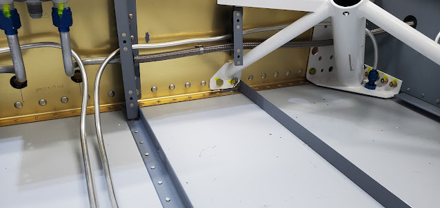
Time to run the brake lines! The brake line exits the fuselage at the base of the gear tower weldment.  The fitting has a 45 degree angle on the exterior side to parallel the gear leg.


Running the 1/4" aluminum wasn't too bad, although it's virtually impossible to make it straight.  It comes shipped in a coil, so by the time you uncoil it to start running it through the gear tower, then bend and twist it to get the entire length of it through the brackets, it's pretty wavy. For the left side, I flared the outside end first and then threaded the tube through to the center.  That was a lot of tubing to push through (it goes to the center then runs all of the way to the firewall)!  For the right side I started in the center and just pushed the smaller length to the outside, then flared the tubing in place.


I gave up trying to use the tubing bender to make any of the bends in the center section or at the firewall.  It was easier to just put the spring bender on and bend them in place.  It looks a lot better in person than in the pictures at least.  Van's suggests sandwiching the center runs in between a couple of pieces of foam to stabilize them, but I think I'll probably just glue down a few zip tie mounts instead (I'll wrap each line with some silicone tape to pad them under the zip ties).  The entire center tunnel of the floor ultimately gets a cover to hide everything.


At the firewall the lines exit from the center cover and pop up and over the firewall brace and over to the fittings that tie them into the actual brake pedal lines.  The lines that go to the brakes are nice, teflon stainless braided lines.


A few days ago I stopped working on the brake pedals because I was two bolts short.  I ordered new bolts, which haven't arrived yet, but in the meantime I stumbled on a random bag of hardware and there were the bolts!  I guess you can never have too many extras.  After bolting the left pedals to the brake cylinders, the next step was to put all of the elbow fittings on the cylinders. 


Most of the fittings are brass elbows that connect to the plastic brake lines, but the last fittings in the series (brake reservoir to right brake cylinders to left brake cylinders to brakes) are normal AN fittings that connect to the braided lines I installed on the firewall. I used Loctite 567 sealant on all of the fittings.


According to the drawings the AN fittings for the braided lines need to angle outwards instead of inwards like the other side.  I will have to wait and see how this ends up working.  I don't want the braided lines hanging over the pedals at all where I could accidentally catch them with my feet.  My guess is there isn't enough room to angle them together towards the center though. I'll figure it out with some creative zip ties locations.


It seems kind of flimsy, but the connection through the firewall to the brake fluid reservoir is just a plastic T fitting.  It's a lot like the pitot/static fittings that the plastic lines snap into.  I suppose in reality there shouldn't be significant pressure going this direction to T, and it just needs to be leak free to keep the brake lines full.


Last up for the brake assembly was to run all of the plastic lines (I guess they're not really "plastic" - pretty tough stuff).  These connect to the elbow fittings by inserting a brass ferrule in the line using heat and tightening it all up using a nut and compression ring. I drilled holes in the center hanger and put snap bushings in place.  The lines from the right side bottom cylinder exit connect to the top of the left cylinder.  The lines coming from the brake reservoir connect to the right side top elbows.


That's it for the brakes for now.  They're pretty much ready to install in the fuselage and plumb.  I'm going to wait to do that until I've got as much done around the firewall as I can though.

For a change of pace I decided to start building the landing lights.  This portion of the lights was pretty straight forward - no soldering like there will be for the strobe and position lights.


Here's the finished product.  These will fit in the leading edge of each wing.  The light with the diffuser on it is the taxi light. The assembly can be wired so that all 4 lights are on for landing, but only the diffused light is on for taxiing to keep from blinding other pilots.


Friday, December 29, 2023

Fuel Lines

I have the new fuel lines now, so time to start the fight of getting those installed.  Since the lines already have the fittings installed, they won't fit through the existing holes in the brackets as they run from the fuel selector valve out to the side skin.  As should be expected, opening up the small holes in the four brackets was of course not as easy as just upsizing the hole.  The hole for the fuel line is so close to the hole for the brake line that upsizing would make them overlap.  The fuel lines came with rubber grommets vs the plastic ones, so perfect holes aren't really necessary.  To keep the holes from running into each other, I used a unibit and slowly chewed away at just one side until I had a fairly large hole started and a different center to reference.  It's more oval now, but with the grommet is fine.  In an ideal world I would have just taken the bracket to the drill press and clamped a sacrificial piece onto the part to put a new center in and used that as my guide, but a couple of these brackets are permanently riveted to the spar carry through.


The professionally made lines are beautiful compared to my attempts using the 3003 aluminum.  The main downside is that the extreme bends required to go from the gear weldment out the skin means they don't exit straight out, but point pretty far forward instead (you can see how it's squishing the grommet and not going straight through).  I emailed TS Flightlines to ask if there was anything I needed to be wary of in terms of bend radius.  He said that even though the lines are quite stiff, they'll actually take a lot more of a bend than most people think.  He said over time they will set into a position, so once they are attached to the tank outlet, it'll be fine.


The flexible lines transition to aluminum at the fuel selector valve and fit perfectly.  Before I start the next step of plumbing the boost pump, I need to jump over to installing the brake lines.  Those have to wind around the fuel lines and run up the center on the floor, so I need those done before the boost pump is in place (sets over the top of the brake lines).


Wednesday, December 27, 2023

Brakes & Lights

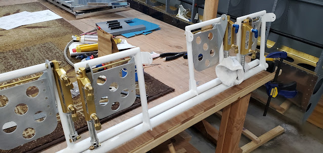
I put castle nuts onto each end of the pivot rod on the brake pedals and secured them with cotter pins (this normally takes one bolt on each side, but I threaded and drilled a brass rod so it's a single piece and won't bind with flexion as easily).


The bottom (top in the picture) of the brake cylinders have a tab that bolts to the brake pedal arm. For some reason that tab is curved on one side and the plans call for a stack of washers to fill the space.  I don't like how the washers let the cylinder rock around, so I printed a spacer with a concave surface to match the cylinder shape.  I was short two bolts, so have to wait for a hardware order to arrive before I can finish the other two pedals.


The FlyLeds wing and tail light kit arrived.  It's hard to believe that these tiny LEDs can possibly put out enough light, but apparently they're pretty incredible.  Lots of soldering to do first though!


Sunday, December 24, 2023

ADHRS Bracket, Almost 14 Mod & Brakes

I bounced around to a number of different things today.  That seems to be the case more often than not now - working on one thing, then moving on to something else while I wait for parts or while I do research on how something is supposed to go together.  For the seat back brace, I'm waiting on a part so I can remake one of the side supports.  I continued to fit the center portion of the support together, but ran into another problem that I've emailed AntiSplat about (the company who sells the Almost 14 mod).  The center cap that goes over the flap housing is supposed to just slide over the top of the Van's housing, line up with the factory holes and then bolt to the seat brace.  I'm not sure if I'm doing something wrong or if I have a wonky part.  When I line up all of the holes for the flap housing, the cap doesn't even come close to laying against the horizontal brace.  So I put a pin in that task and move on to something else while I mull it over.

A long time ago I purchased an ADHRS mount from Van's.  I'm going to mount the ADHRS sensor in the tailcone just behind the baggage bulkhead.  The sensor has to be mounted so it sets level in level flight.  The Van's mount already has the math done to account for the slope of the tailcone, so it was just a matter of sliding the mount in place against the center brace and one of the J stiffeners until a couple of tabs hit.  I used my right angle drill and drilled all of the holes (it'll just be pop riveted - there's no need for incredible strength here), then pulled the bracket out and put it in the "to be primed" pile for the spring.


I don't want to actually put the rudder pedals into the plane until I have the fuel line and other aluminum brake lines run (the fuel lines go in first - my pro built ones are supposed to be here this week).  I still need to locate and drill the holes in the brake pedals for the brake cylinders though.  This is not as straight forward as taking measurements and drilling the pedals all the same unfortunately.  The way the rudder assemblies are set up, the rudder pedals aren't at the same angle, which means the brake pedals can't be set the same relative to the angle of the rudder pedal or things will feel really out of whack.  For the rudder pedals, all that really matters is that the lower portion where your foot pushes is the same from your left to right foot.  It's a round tube you push on, so it doesn't really matter what angle the vertical tubes attaching it to everything else set at.  However, because the brake pedals are big and flat, it would feel very strange if they were set at the angle of the rudder assembly they are attached to - the neutral angle would be different for the left and right foot.


To attempt to get the brake pedals as close to each other as possible, I first clamped the rudder pedals to each other to make them even.  Then, I clamped the brake pedals to each other using a file.  I also stacked a couple of tongue depressors behind the file to give the brakes a tiny bit more angle back so they're not as easy to accidentally hit if my feet are on the rudder pedals.


All of this is done so that each brake cylinder can be independently located.  Because each brake sets at a different angle relative to the rudder assembly, the cylinders don't line up at the exact same location on each pedal tab.  I didn't have a great way to use a marker to mark the cylinder hole location, so I grabbed a 3/16" bit and scratched the brake tab while swinging the cylinder in a little arc.  With that position, then I'll just find the center of the tab and drill the hole.  Fingers crossed all of this works!  That's for tomorrow though.


Saturday, December 23, 2023

AntiSplat Almost 14 Mod

I'm still waiting on my fuel lines to be delivered, so I jumped to working on the Antisplat seat back modification.  This will be kind of a handful to do because it's not specifically designed for a tip-up canopy, but I think it'll be worth the effort in the end.  The biggest headache right out of the gate was due to the fact that I had already drilled holes in all of the original parts, which meant that the new pieces in the modification had to be made to fit the original holes.  It's going to be pretty much impossible to explain the modification, but I'll give it a shot.

The original seat back brace comes out and is replaced by an aluminum box that is riveted to the vertical bulkhead pieces and extends back about 4", where the new brace will attach.  The biggest problem was trying to get accurate holes drilled in this box, which is sandwiched in between two existing parts that are already drilled.  That wouldn't be a big deal if all of the parts were rigid, but there's a lot of wiggle room in the parts still, so it's extremely difficult to put the box in place without impacting the location of the holes in the parts that are on bottom and top of it.  It literally took two hours of back and forth clamping and moving and testing to get the left side in a spot where I was confident enough to drill the holes through the top and front of the box.


I put the right side box in place and got most of the holes drilled in it, but the existing holes in the plate that goes on top of the box were just too far off once everything was positioned, so I'm going to remake the plate (ordered a new piece of aluminum) so I can drill fresh holes exactly where they need to go.  You can see how the new brace works at least - instead of the seat back only going back as far as the vertical bulkhead piece, with the new brace it can recline a bit further.  With the seat adjuster that is hinged to the seat back itself, if it goes in the wedge on top of the brace, the seat sets at the exact same position as the original Van's design.


Because the seat brace sets further back than the stock design, I also have to modify the flap covers.  I'm still trying to figure out how the mod works here (no instructions with the mod, just the raw material).  There is a new welded aluminum box that extends the original flap cover back to the seat brace, but it's not fitting all that well.  I think I need to redo some of my original bends and cuts to make it all fit.


While I was working on the seats, I noticed that the seatbacks don't actually fold all of the way forward at the lower hinge because they hit the attachments of the vertical flap cover.  I cut a square chunk out of each of the attach points to allow the seat backs to clear them.  This will let me flip the seats forward to slide stuff into the baggage area.


Sunday, December 17, 2023

Fuel Lines & Almost 14 Mod

The 3/8" fuel line runs from the wing root, through the side skin, around the gear tower and over to the fuel selector.  All of the online blogs mention how hard it is to get the 3/8" line shaped and through all of the bends without kinking it.  I started at the middle by the selector and weaved it through and around everything to the outside.  The first attempt took forever, and ultimately ended up like everyone said it would - with a kink.  I have a pipe bender, but there's no way to use it because all of the bends have to be made in place.  I have a spring bender, so used that where I could, but the extreme bends to get the tube to exit around the gear tower and go through the skin were just too much and the tube kinked.  The second attempt went a lot better.  I got the 90 degree bend done to the fuel selector and got the bend around the gear tower done.  The final bend out the skin did me in again though, and the very last bend kinked the tube again.

With that, I decided to do what most people do and ordered pre-made fuel lines from TS Flightlines.  They CNC bend tubing for the fuel selector area as well as all of the spider web of tubes that connect everything to the fuel filter and boost pump, then the rest is made of flexible, braided lines. I went ahead and also ordered their brake lines that run down the gear legs.  The plans have you run 1/4" aluminum lines down the gear legs to the brakes, but there are a lot of reports of the flares at the brakes cracking over time since they get tightened and loosened for brake maintenance.  TS Flightlines makes a braided line that should hold up better, partially because of the flexibility, and partially because the fittings they use are a tougher material than the aluminum tubing Van's uses.  I'll use the 1/4" aluminum tube for the internal brake lines out to the fittings that exit out the fuselage floor and the gear towers.


While I wait for the premade fuel lines, I moved on to a few other things.  The flexible lines from the brake pedals will route through fittings attached to the firewall to the 1/4" hard lines that will go down the center tunnel, underneath the fuel boost pump and then out to the gear legs.


I have been waffling on whether or not to do the Antisplat Aero "Almost a 14" seat brace mod.  This mod replaces the standard seat back brace with a much more robust, but narrower one that moves the seat back location back about 4".  I don't really need the extra room that tall people need, but the ability for one seat back to be at the "normal" location and the other to be 4" back adds a feeling of extra width simply because pilot and passenger aren't shoulder to shoulder.  Virtually 100% of the comments I've read have said it's the best mod they ever did for the plane because of that.  The one major downside is that the mod is designed for the sliding canopy.  The tipup canopy will add some complexity to fitting it because of how the canopy latch mechanism works.  There are a couple of different ways to deal with the canopy latch.  I'll deal with that down the road when I fit the canopy.

You can see the difference between the braces in the picture.  The standard brace that I pulled out is on the bottom.  The new brace is the narrower one on top (I think it's steel vs aluminum - it's much thicker and heavier).


Sunday, December 10, 2023

Brakes & Fuel Selector

First up tonight was installing the brake fluid reservoir to the firewall.  Because of the variability in firewall forward design, pretty much everything that goes onto the firewall has to be laid out and drilled.  Some pass throughs I will probably wait on until I have the engine to be sure I get them in the right location, like the holes for the throttle cable, mixture, etc.  The brake cylinder doesn't depend on the engine type, so I went ahead and put it where Van's calls out.  It was a little fiddly, since there are two bolt holes to drill, but then a larger 1/2" hole centered below them for the brake line fitting.  After a lot of measuring of the part and double and triple checking, I drilled.  Thankfully the hole ended up where it needed to be.  I still haven't decided if I'll put fiberfrax on the front side of the firewall or not (fiberfrax with stainless foil over it - for greater fire resistance and maybe an extra 60 seconds when I need it most.  There are a lot of arguments about whether or not it really matters.).  If I do, at some point I'll have to pull this cylinder and all other items mounted to the firewall off so I can make a template to cut out mounting slots in the fiberfrax.


I torqued down the bolts, so it's all ready for brake line fitting.


To get started on the fuel system, I took apart the Andair fuel selector valve to change the fittings to the orientation I need.  Based on the directions, I cut a 1 1/8" hole in the aluminum mounting plate that connects it to the wing spar carry through bulkhead.  I shouldn't have trusted the instructions.  Apparently they've changed their design and didn't update the instructions.  The part of the valve that sticks up through the mounting plate is now just 1", not 1 1/8".  It doesn't really matter since mounting screws hold everything on, but with the selector flopping around in the mounting plate, it was really hard to get it lined up for drilling the mounting holes.  3D printing to the rescue!  It took all of 15 minutes to draw and print a collar (the black ring you see around the top of the selector) so that I could more easily center the part in the 1 1/8" hole.  With that done, I drilled the 3 mounting screw holes (not shown in the picture below - the two holes in the plate by the big center hole were pre-drilled by Van's for their own fuel valve.  These holes will get covered up.).


I put nutplates on the valve to make it easier to attach vs using bolts and nuts.


Here it is temporarily installed so I can use it to lay out the fuel lines.  I countersunk the top cover to accept flat head screws vs pan head.  I had to place an order from Aircraft Spruce tonight, so I ordered a few stainless screws.  I think they'll look a lot nicer than the gold cad plated ones.

I started measuring and thinking through how the fuel lines would go.  The fuel line is still soft aluminum 3003, but  it's 3/8" and has a thicker wall thickness than the 1/4" vent tubing.  It's much more difficult to bend by hand.  I practiced a few flares to ensure I knew what changes had to be made for the bigger material (turns out it's the same 4 1/4 turns by the flaring tool as the smaller 1/4" tubing is), then cut a piece to length and made my first bend....and subsequently put a kink in the pipe because I hit it on the edge of the tubing bender.  So scrap that 2' of tubing!  That'll be my practice piece I guess.  Van's gives you juuuust enough tubing to get by with maybe one oops.  I don't like that pressure to potentially put a piece of fuel line in that I'm not 100% happy with, so I decided to order a couple of 12' rolls of extra 3/8 and 1/4 tube.  Of course it's backordered until February like everything these days, but it's super cheap, so worth having on the way so I feel confident in the end result.

Saturday, December 9, 2023

Fuel Vent - Right

The right side vent line went much faster than the left.  Next up are the fuel lines themselves.


Friday, December 8, 2023

Fuel Vent Line - Left & Misc

Work has been pretty all consuming the last few weeks, so I haven't had much time in the garage.  I finally had some time to decompress tonight, so got a few things done though.

Just a random tool - I had no idea this existed until I heard someone mention it online.  It's a chuck for my right angle pneumatic drill.  The drill only takes threaded drill bits, which can make life difficult when you need a very specific size bit.  Threaded bits aren't the easiest things to track down (when you just need one and not 50 of one size), so usually have to be special ordered and the shipping costs 10x what the bit does.  This chuck is quite small and threads into the drill, but then can accept regular drill bits.  Having this earlier in the build would have been a huge help.


The vent line fittings that protrude through the forward bottom fuselage skin need some protection from insects, so I prosealed a piece of screen over the external end.  Once the proseal dries I'll trim the excess off.


Since I was mixing up a batch of proseal, I decided to also seal up the gap where the gear leg tower exits the fuselage.  This area will be covered up with a fairing, so it's not visible, but it would allow an awful lot of cold air to sneak into the cabin if it were left open.  The picture is deceptive - it's really a fairly thin line of proseal that will remain once the tape is pulled.


The instructions didn't mention this yet, but I decided to put the rudder cables in place.  The reason being that the fuel vent line has to bend around the cable in one location, so I wanted the cable in place to make sure I gave enough room.


My first try at bending and flaring the soft aluminum vent lines was laughable. The tubing Van's uses is very soft, making it easy to shape, but because of that, it's also really tough to create straight runs.  It doesn't help that it ships coiled up to begin with.  After a few failures, I relearned how to make acceptable flares (note to self - for 1/4" soft aluminum tubing, it's 4.25 turns of the flaring die after first contact - that makes a flare that is in the middle of the .34-.36" flare diameter range).  The first vent line run comes in through the side skin from the wing root and turns forward.  It passes through the vertical bulkhead using an elbow fitting.


This elbow fitting was a nightmare to get in place.  A 30 second job of screwing on the nut on the back side was really a 2 hour bout of frustration and red neck tool making.  The vertical bulkhead has a lip that curls around the back, and no wrench or socket can get at the nut.  I finally had to chop down an old wrench so it was only about 2 inches long and grind the sides away until it would fit in place.  I couldn't get any leverage to really torque the nut down much, but it's as good as it can be.  I'll put some proseal or loctite on the nut just to keep it from backing off due to vibration.


The big bear for the vent line was the forward portion that runs from the elbow fitting, up and around the rudder cable, up to the longeron (so it's above the level of the fuel tank) and back down to exit at the floor.  The bends were bad enough to just get in the right place, but then they are also all in different planes from each other.  For example, in the picture it looks like the top portion starts with a 45 degree angle off of the vertical and just runs forward then back down.  In reality, it comes off the 45, then straight forward, then dives inward a couple of inches under the top firewall bracket, the it takes a sharp curve down and back to the outside, then straight down before it finally goes back towards the centerline and out the bottom.  I'm not embarrassed to say this was attempt number 2!  I got the first one nearly completely done, then on the last 90 degree bend to the floor fitting, I crimped the tubing.  I have a tubing bender that makes very nice bends, but I couldn't use it (or even the spring benders) on that last bend because there is only about 1" of length.  The nut and sleeve have to go on before flaring of course, and when they're on, the length is so short that none of the bending tools can be used without hitting the nut.  Fingers don't make very easy 90 degree bends.  My second attempt worked out well enough to call it done though.  Tomorrow I'll tackle the right side, which I'm guessing will go much quicker.