Friday, January 31, 2025

Panel Design

I have very little to show for the last week or so.  I've mostly been confined to couch duty - babysitting the dog after her surgery.  I just feel too bad putting her in a cone 24/7 and leaving her confined alone.  If I'm there she at least gets the cone off.

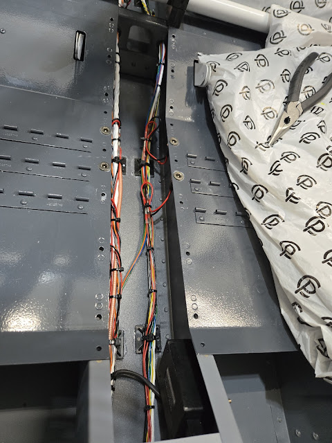
The wiring up the center tunnel is finished (I hope), so I reinstalled the boost pump and fuel selector.  Of course that wasn't as straight forward as you'd think it should be.  Every time I add a part, the newest area of interference gets discovered.  The nutplates on the top left side of the fuel pump plate were right on top of the wire runs, meaning the screws would be driven right into the wire bundle.  I had to pull up the cable mounts and move them inboard as close to the brake lines as I could. 


I still have a number of big things I can do before I route the wires to the subpanel/panel, but that day is approaching.  In order to do that, I have to narrow in on my eventual panel design.  It doesn't have to be perfect yet, but I do need to have a general idea of where things will go in order to split out the wires into smaller bundles and run them to the correct locations on the subpanel.  I haven't taken the time to actually lay the panel out in CAD software yet (not sure if I will - I can either just lay the panel out by hand and cut it, or I could lay it out on the CAD and then have a vinyl sheet printed to lay on top of it and use as a cutting guide.  The benefit of going that route is that I could then use the same file to have an actual vinyl overlay done, with all of the labeling just printed on it.).  I found an online panel planner tool to play around with the general layout though.  It's not precise enough to use for anything final, but at least provides a visual to then do my final design off of.

I started the design with my ultimate IFR panel, then went backwards from there to get a more basic VFR panel.  This is the IFR version:


For the VFR version, I removed the IFR GPS and the second glass screen.  I will cut the panel for these and put all mounting brackets in place, but then just put cover plates over the openings until I'm ready to go IFR (or I could 3D print some boxes to inset in the openings I suppose).  If I decide it's handy, I could put an ipad mount on the right hand side and essentially use my ipad as a second screen.  Or, if cost isn't a factor, I may just go with both of the AFS screens right out of the gate.  I'll just play it by ear.


Saturday, January 25, 2025

Final Cockpit Wiring

My shielded wire and a few other odds and ends arrived.  The ELT can receive coordinates from a GPS and then send those coordinates out, and that's what the extra wire is for.  The connection method they use is really laughable though. They have you solder four wires to little itty bitty DIN pins.  I'll be pretty shocked if they last.  The pins are about 1/16" long, very thin and not far apart from each other, so holding a wire up against them during soldering is next to impossible.  This is probably why the instructions say to fill the cavity up with RTV and then wrap it all with tape.  Pretty ridiculous for a certified system.  If it ever fails I'll just cut the DIN connector off completely and use individual connectors.  The main thing I dislike about the DIN connector is the fact that the male and female pieces don't positively lock with each other.


Since the DIN connectors don't actually lock together, I mounted the wire above the ELT and zip tied the two connectors so they can't separate.  The short white wire sticking out from the aft connector is a test wire.  Once I hook the GPS unit up, I can use this test wire to see if the ELT is receiving the signal.


I finished wrapping up the left side wiring.  At least I did until I realize I forgot something.  It's starting to get organized!


The hodgepodge around the fuel selector looks like I mess, but in reality it's actually not too bad.  There's good clearance around all of the wires and fuel lines.  My next step tomorrow will be to re-mount the fuel pump and make sure there are no interference issues.


Monday, January 20, 2025

ELT & Aft Top Skin

My latest head scratching session led me to my final ELT antenna coax routing.  I pop riveted a number of small cable mounts to the J stringer and drilled a hole for a snap bushing in the middle bulkhead.  It's outside of the picture, but at the next bulkhead back, the coax runs up the bulkhead (alongside the static line) to the antenna location.


Here you can see the ELT coax run up the aft bulkhead. With that done, I measured the elevator pushrod and threaded the bearings in to the right length (at least according to the plans), then bolted it to the elevator bellcrank.  It's starting to get closer and closer to done back there!


I've really wrung my hands over putting the top skin on.  I want to have as much as possible done in the tailcone before the lid is on so I can limit the number of times I have to crawl back there!  I think I'm finally at that point though.  I clecoed the skin on, but I think I'm going to have to take it off and cleco it back on in different order.  It all fits fine except for the aft right side, which is off by just enough to make the holes tough to get clecos into.  I've found that for whatever reason, parts can fit perfectly one time, then if they are clecoed on starting in a different spot they can be way off.  I just have to figure out what order to cleco the skin on so it stretches the right way.


Sunday, January 19, 2025

Front Wiring, Flap Sensor, Static Line

The pictures keep looking the same from day to day, but I promise that it's the picture of progress! More head scratching and many hours just standing and staring led me to do a little more shifting of wires in the front center tunnel.  The driving force in all of this thought and moving things around is to try to minimize parallel runs of certain wires with each other, the worst offender being the transponder coax.  From what I've gathered, it's an extremely potent system, and if there is going to be interference, it's going to come from the transponder.  The RG400 coax is double shielded and really should be fine keeping in/out any interference, but occasionally people still have problems with it.  The RV is so small that I can only do so much though.


As best as I can tell, I'm done with the run going up the left side of the tunnel.  I re-zip tied the wire bundle for the 50th time and put some spiral wrap on it to give a layer of protection between the wire and the floor.  The right side bundle is all ready to finish up, minus one last group of wires from the ELT.  I'm waiting on some shielded wire to arrive to finish that ELT/GPS connection, then I'll be all done with wiring to the panel.


My first approach to attaching the flap position sensor clevis to the flap control arm was to just use a small piece of aluminum held by a single adel clamp and bolt.  That was probably a fine approach given that the position sensor requires very little force to move, but I didn't like the fact that the piece of aluminum could potentially rotate around the bolt if anything loosened up.  I remade this piece (that the position sensor clevis attaches to) so that it is now held rigid by a second adel clamp.  Now there's no way it could rotate around the aft bolt and cause erroneous flap sensor readings even if the bolt loosened up.


I think I finally landed on how I will route the static line up to the ADAHRS.  I'm just going to zip tie it to the canopy latch teleflex cable to take it from the longeron up to the top skin and ADAHRS.  The teleflex cable is relatively rigid, but will still vibrate, so I want a way to hold the ends of the static tube as it enters the T (the T is in place to also allow the static line to go up to the panel for the G5).  I made a mount that the T bolts to, and extended it to also have a snap bushing.  The mount will be riveted to the longeron.  Even with vibration along the teleflex cable, the snap bushing should isolate the T connection enough...I think.  My other option was to put the T further aft and run the static line up a bulkhead then forward to the ADAHRS.  There was nothing wrong with that approach, I just had to choose one.

Wednesday, January 15, 2025

Zip Ties x1000

I'm not sure I'll be able to describe everything going on in the plane right now.  Lots of rat's nest looking areas that I'm combing through.  I routed the ELT "phone cable" down the floor and up and around the vertical brace.  I'll finish the left side once I mount the wings and pull the AOA line through.  I did pull a length of 1/4" tube through the conduit for the pitot line.  The pitot line won't be a single length from the wing, but will have a T in it since it also needs to run to the panel for the Garmin G5.  The AOA line only goes to the ADAHRS at the back, so it'll be one continuous run from the pitot all the way back to the ADAHRS.


The pitot line will have the T in the first rib bay just behind the wing spar.  I wasn't sure I would be able to fit it in, but after A LOT of pushing and pulling I was able to get a 1/4" line (the blue one) in the spar holes with the two coax lines.  There is definitely nothing else going in that run!  I ran out of blue tubing (the pitot tubing is also blue in the wing), so the pitot line going to the ADAHRS is white.


It probably doesn't look like much has changed, but the area in front of the spar (and especially at the fuel selector) is getting much more organized.  Routing the coax (and now pitot line) behind the fuel and brake lines looks like it's going to work much better than how I had it routed before.  There's actually more space around everything than the photo suggests.


Tuesday, January 14, 2025

Wire Re-re-re-routing

Minimal pictures of the progress, but today I did a bunch of wire rerouting, again.  Except for a few final touches, everything aft of the wing spar carry through is in pretty good shape.  Another couple of sessions and I should have the wiring up to the firewall as finalized as it can be until I build the panel itself and bring wires through the firewall from the engine.

I've been scratching my head over how to handle the coax cables coming through the outside portion of the spar carry through (exiting under the gear leg tower).  The hole they come through is almost directly behind the fuel line.  Since there's really no way to separate everything, I decided the best approach was to simply protect it all from abrasion.  I grabbed some clear vinyl tubing and zip tied it around the fuel line.  Once I zip tie the coax cables together, there won't be much movement possible and the tubing will protect the cables and fuel line.  I did the same on the other side.


The biggest problem area for wiring is where it all comes together in the center tunnel around the fuel valve.  Ever heard the saying "10 lbs of @$!* in a 5 lb bag?"  I originally had all of the wires that exited from the upper holes (both from the spar carry through and the upper hole in grey brackets) come over the top of the fuel lines and then down to the floor.  I thought that was going to work, but then I grabbed the fuel valve housing, and it turned out that there was just no room.  It's obvious that the RV9A is a 25 year old design - the wiring needs have gotten a lot more complicated over the last few decades!

I'm waiting for the glue to dry before I strap everything in place, but I put a couple of new cable mounts on the carry through.  The coax will go to the center cable mount and then go from there down and out to the wire runs on the floor.  There's a lot more room in that center to outside path vs going straight down behind the fuel lines. The other wires can go straight down to the floor since they are much more flexible than coax and can make tighter radius bends.

I riveted the elevator bellcrank shield in place.  This will hold the cable from the ELT that goes to the panel (at least the telephone wire that goes to the remote switch - I haven't decided if the wire that goes to the GPS will take the same route or just go directly through the conduit on the ELT side.  The only reason the telephone cable is crossing over is so that it doesn't run by the transponder and run with that coax on the way to the panel.  The transponder is so high powered that it's known to cause false triggers of the ELT.).  The AOA and pitot lines will also get mounted to this shield on their way up to the ADAHRS.

The plans indicate the length the elevator pushrod should be, but there's no way to set the overall length with the bearings before putting it all in place.  I took the measurements from the plans and made a little template to bolt through each bearing and screw the pushrod in to the right length.  I hope the plans measurements are actually accurate, but I won't find that out until the elevator is in place.

This bolt going through the front bearing took me a solid hour to put in.  There are two thin washers that go on the inside between the bearing and the control column. I had to try about 100 different methods to hold them in place while I put the bolt through!  Between the tight tolerances and the inability to get my hand in between the ribs, it was a nightmare.  


Monday, January 13, 2025

Coax Connections

I put a some work in today, but there's not a ton to show for it.  I put 4 BNC and 1 TNC coax connectors on.  The two coms, ADSB and transponder antennas use BNC and the Garmin GA36 GPS antenna uses a TNC connector.  This was my first round of crimping coax connectors, so it took a little time to get the process figured out. I will wait to terminate the ends of the coax at the panel until I have the panel actually in and devices in place.


Sunday, January 12, 2025

Wiring Cleanup & Doublers

I received my latest order that had my Garmin GPS puck and a few other odds and ends in it.  Something I got to try out were floating nutplates.  They are similar to regular nutplates, but the center lug with the threaded hole is floating and can move around a little.  Since I didn't have the GPS in-hand when I made the doubler, I had to just drill the holes based on measurements.  History has proven that no matter how careful I am, holes laid out by hand and drilled manually are never 100% accurate.  The floating nutplates give enough wiggle room to make up for the holes being off by a decent amount.

Since the top skin is still off the plane, I just back riveted the doubler on.


Moving back to wiring - it felt like I just stood and stared at the plane for a couple of hours today.  Lots of pondering going on!  The pitot and AOA lines will come back to the rear of the plane via the conduit below the baggage floor.  Then they need to somehow get up to the top of the tailcone where the ADAHRS unit is.  I decided I'll run them up the center brace, but I don't like the idea of the tubing just being looped up and over the elevator bellcrank.  It would be a very bad day if one of those tubes ever got caught on the bellcrank.  I decided to make a guard to go over the bellcrank.  I'll put cable mounts on this to run the tubing up to vertical brace.


The wiring going from the center section bulkhead forward is starting to come together.  I'm still not quite sure how I'm going to handle routing all of the wiring around the fuel selector though.  The bundles are pretty thick and run into some of the fuel lines right where it's all butted up against the bulkhead.  That'll be another day of standing and pondering.


Saturday, January 11, 2025

Center Section Wiring Cleanup

I've been dragging my feet on starting the riveting of the bottom skins of the left wing.  The reason?  The wing was facing the wrong way, making the light bad and access difficult with vehicles in the garage.  Maybe not the best excuse, but that's the excuse I had.  I didn't actually start any riveting today, but I did take the time to move benches and everything else so I could swing the wing cradle around.  I spun it so the left wing is now facing my benches and tools.  Now I have something to do when I need a break from other tasks.


I'm slowly working my way forward with wiring cleanup.  While I think I have all of the wiring pulled that I need, it also won't surprise me if I find out later that I'm missing something.  That will just allow me to continue my ritual of cutting off at least two zip ties for every one I put on.

I glued a cable mount inside the flap motor housing and ran the flap motor power and position sensor wires down the housing and into the center tunnel.


There are a number of wiring offshoots in the center tunnel between the seats (to get to the seat heater jacks and roll trim servo), but it still cleaned up fairly well.


After I got most of the center tunnel wiring done, I reinstalled the roll trim servo.  I also slid the elevator pushrod back into the tunnel.  It's just laying on the floor for now, so it won't be as close to all of the wiring as it looks in the picture.  I need to measure the pushrod again, which is going to take some doing.  The manual shows the length it should be, but you can't actually install it with the end bearings in place.  So I had to unscrew the bearings to get it in place.  It's not possible to get a tape measure on it, so I'll have to go with a string or something.


I've decided to take certain wires out of the terminal blocks and instead just use butt splices when I'm ready to connect the wings.  Most power circuit wires are fine in the terminal blocks, but low voltage data wires are apparently more sensitive to loss, and the terminal blocks can sometimes cause enough noise in the signals to be problematic.  On the left wing, there is only one questionable wire - the pitot heat status, so I pulled that out of the terminal block.  I also took the screws out of the block and added star lock washers to them.


The right wing has more data wires because of the autopilot servo.  In hindsight, it would have been easier to just use a connector of some sort vs the terminal block, but next time I guess.


I originally thought I would just run the antenna coax through the large lightening hole in the seat rib (like the above photo), but I couldn't figure out a great way to secure it.  I could put some edging on the hole to protect the wire from rubbing, but the coax would still be unsecured and vibrate.  I decided to punch through the rib with another hole.  I did this on both left and right sides.  Not shown in the pics, I also glued down a number of additional cable mounts to secure the corrugated tubing.


Wednesday, January 8, 2025

Coax Runs

Because the rat's nest wasn't quite bad enough yet... After being back ordered for 3 months, I finally received the antenna coax (RG400) and got started pulling it for the two com antennas, ADSB, transponder and Garmin GPS antenna.  I still have to crimp connectors on each end (I'm just going to do one end and then will do the other end once all devices are in place and I cut the coax to the final length).

After going back and forth with both Dynon and an antenna manufacturer, I am comfortable with my com 2 and ADSB location behind the baggage bulkhead.  It was obvious Dynon wanted to only officially say that the recommended distance between ADSB and the com antenna was 3 feet, but once I pressed them on why, they kind of backed off of that.  They said that their general guidance on distances for antennas is "stacked in favor of more room is better" but that in reality the com and ADSB are unlikely to see issues being closer together.  Worst case scenario is that I could notice ADSB traffic dropping out momentarily when transmitting on com 2 (which won't be common use - it'll typically just be used for monitoring).  That's a non-issue and hardly a reason to bend over backwards to try to separate the antennas more.

I also heard back from Don at Delta Pop Antennas.  He's known for being THE guy for experimental aviation antennas.  He said there's hardly a single GA plane on the planet that could satisfy every manufacturer's recommended installation instructions for antennas.  Based on his direct experience and years of asking pilots about their own experiences, he thinks my setup will be just fine.

So with that uncertainty checked off, I went ahead and dimpled all of the holes for the aft doublers.  They're ready to rivet once I have a second set of hands to help get under the fuselage.  You can see the coax runs for those two antennas, plus the GPS antenna that is on the top skin.

One thing I did change after doing some research was the location of the wiring that goes from the ELT to the panel for the remote trigger.  I probably would have bought a different ELT had I known how this one was put together, but that ship has sailed.  This ELT uses generic telephone wire to go to the remote trigger in the panel, and apparently some people have issues with the ELT going off when it shouldn't.  The assumption is some sort of RF interference, probably through that cheap telephone cable.  I'm going to move the routing of that cable so that instead of the direct run forward, which would have it ultimately go right by the transponder antenna and run alongside that transponder wire up to the panel, it crosses over to the other side of the baggage compartment and then goes forward.  That should at least keep it away from the high power transponder and help with interference issues.


I think I'm pretty well set in terms of the rear aircraft wiring now.  That means I can finally start tidying things up!


Friday, January 3, 2025

COM 2 & ADSB Doublers

I've decided to switch up my antenna plans a little and put one COM and the transponder up under the seat pans, then the other COM and ADSB behind the baggage bulkhead.  That seems to be the best of all worlds in terms of separation and coax runs.

Drilling holes in the skins never gets easier though!  I was careful to set the aft doublers parallel to the direction of flight (the antennas are fins, so best not to get them canted off to one side).  If I had put the transponder and ADSB both back here, I would have had to slide the antennas out to the edge as far as they could go to meet the 2 foot separation requirement.  That hits the curve of the skin, so less than ideal for the doublers.  Based on what I learned online, including a post I saw on the Dynon forum by their tech support a few years ago, I decided to move those locations in a few inches so they'd land on the flat portion of the skin.  Apparently the COM and ADSB antennas don't have the same issue with interference as the transponder antenna and COM does.  The transponder is a transmission powerhouse, but the ADSB unit is just a receiver (coupled with the fact that it operates on very different frequencies than COMs do).

All that being said, no sooner had I drilled all of the holes than I got reply from Dynon tech support that I had sent a while ago.  This guy said that ADSB and COMs should be 3 feet apart, just like transponders and COMs.  This contradicts what they've said before, so now I don't know who to believe.  My holes are already drilled, so I'm hoping this guy was just groggy from his holiday vacation and not thinking straight!  That got me really digging into their installation manuals, and that made the confusion even worse.  While their manuals may be great relative to the rest of the industry, they're still full of contradictory recommendations.  Depending on which section I was reading, I found three vastly different antenna separation recommendations.  They sure don't make it easy on a guy!  For now, I'm leaving things as-is since I think the ADSB and COM are likely fine without much separation.  If I learn otherwise, I guess I'll get to use the doubler just to patch up the holes and have to make another doubler for use further back in the tailcone.


Wednesday, January 1, 2025

Doublers and More Doublers

I'm not sure what making a bunch of doublers equals, but it's a lot.  I picked up where I left things the other day and finished the doubler for the Dynon GPS antenna.  I attached nutplates to it, then back riveted it to the skin.  The antenna itself (and all others) won't go on until after paint.


Next up is the Garmin GPS antenna that I'll use for the Garmin G5 and for a future IFR GPS.  I don't have the Garmin GPS puck yet (it's on order), but I grabbed the bolt measurements from the install manual and laid out the doubler.  It's a bigger GPS than Dynon's.


The Garmin antenna sets further back and to the other side of center than the Dynon antenna (to meet the 12 inch distance requirement).


The doubler is primed and the skins are match drilled to it.  I'm waiting on some larger nutplates to arrive before I rivet it all to the skin though.  


I'll be getting the two comm antennas and ADSB and transponder antennas from Delta Pop.  They use the same mounting method for all of their antennas, which makes life a little easier.  Whereas the GPS antennas mount using screws, all of these other antennas have studs that are built into their bases (one center hole for the coax connector and two studs).


I went the mass production route, stacked the doublers and just drilled them all together.  I left the center hole undersized for now, since it'll be easier to match drill to the skin if I can drill with a smaller twist bit (as opposed to a unibit, which is necessary to drill the 9/16" center hole in a thin skin).


A lot of people place the ADSB and transponder antennas directly behind the baggage bulkhead at the outside edges of the floor.  Dynon requires that these antennas be placed at least 24" apart.  If I put each antenna right up against the lateral J channel, I can just barely meet the requirement.  The problem with that is that the floor starts to curve before it gets to that J channel.  It's not impossible to deal with (I had to bend all of the upper skin doublers a little), but it would be far, far easier to put the doublers on flat skin.  I don't love the fact that the distance is at Dynon's bare minimum either.  Since the antennas are small and on the bottom, I'm not all that concerned about symmetry.  That ship has sailed already with the GPS antennas anyway.  I decided that it would be much easier to mount the ADSB antenna up by the baggage bulkhead and the transponder antenna further aft behind the next bulkhead.  This easily meets the separation requirement and provides flat surfaces as well.  The locations below are just general locations.  I still need to figure out the exact positioning.


That skin behind that aft bulkhead is a little less stiff and is known to be a spot that sometimes oil cans in flight.  Putting a doubler in the middle of the skin with no other tie in to structure could cause cracking (unlikely, but possible), so I'm going to put the doubler right up against the bulkhead and tie them together with a piece of thin angle.


The last doubler I need is for the ELT antenna.  This is a much smaller antenna, so doesn't need much support.  The common approach is to use a small, circular doubler located by one of the aft bulkheads.  I have to say, it's a little nerve wracking drilling a ton of holes in the skins!