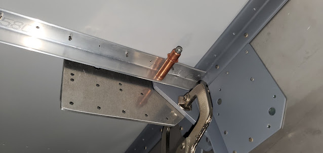
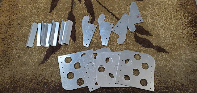
I'm itching to be done with the fiddly spacers and random pieces that take forever to fit but are tough to see progress in. I finished up the fuel tank attach point reinforcement pieces for both sides and riveted the assemblies together. You can see the spacer on the left that goes in between the side skin and the gear attach web, then the reinforcement angle. The spacer is countersunk for two rivets that hold everything together.
The gear attach web then went back into the fuselage. I also drilled the holes in the web and side skins for the fuel line and vent lines. I used hole saws for these holes, but I'm not thrilled with the quality of the cut. They ended up pretty uneven and rough. I think probably just because the teeth on the hole saws are pretty aggressive. I can smooth the holes out, but it will enlarge them a bit. I took a look at the rubber grommets that go in the holes, and they should fit fine even with less than perfect holes.

That all took about 100x longer than it should have, but it's finally done! I switched back over to the brake/rudder assembly. I stacked the right and left rudder pedal assemblies together and trial fit the two plastic bearing blocks that go on each end. The instructions are pretty much non-existent at this point. They basically say to build the pedals and everything else, but that's about it. At this stage of the build, they assume you can figure everything out by looking at the drawings. That's not overly difficult anymore, but it assumes accurate drawings...I just have to hope most are more accurate than what I went through recently with the last few pieces. I still need to rivet together the pedals themselves, but I think I'll wait and do that when I'm ready to prime a bunch of parts. I did go ahead and countersink and deburr the pedals so they are ready to go though.
It's not called out anywhere, but based on the drawings it looks like the holes drilled in the bearing blocks are at a slight angle, meaning they are directional. After some back and forth I got it figured out. I made sure to label right and left, as well and front and top so I can be sure they go back in the same direction once I'm ready to assemble.
Each block has to be drilled to accept bolts that will attach the pedal assembly to a couple of the fuselage skin stiffeners. My drill press vice is far from perfect, but I was able to get the block set up well enough to drill decent holes. I started small and worked my way up to a #10.
The middle stiffener (with the cleco in it) is the part that the bearing blocks rest on. Having the fuselage upside down always makes the mental gymnastics a little harder to do. I can't wait until I can flip it all over so the picture in my head matches reality.
Putting the blocks in place and drilling the stiffeners while they are attached to the skin would be next to impossible, so after measuring where the blocks need to rest, I pulled the stiffeners out. The blocks have a minimum distance they have to be away from the firewall (3"). I added 1/8" to that just to make sure I don't run into issues down the road. I clamped each block to the stiffeners and used them as a guide to drill the holes.
The location of the blocks sets the distance to the pedals. The plans mention that it's a good idea to drill extra holes so that adjusting leg room later on will be easier. I probably drilled far more than necessary, but if I ever sell the plane to somebody with super short legs, they'll appreciate the flexibility. The stiffeners then went back into the fuselage so I could do a trial fit of everything.
It's still all upside down, but pretty cool to see how it all goes together. I didn't tighten up the bolts at all at this point. They're just in enough to keep things from falling out while work on the next pieces (more plastic retainer blocks and a support brace for the middle of the assembly).


